| Drawing 14 - Superheater and Ashpan
|
| 1. Ashpan |
There is an update on the Assembly
page (item 15) showing the removable grate |
 |
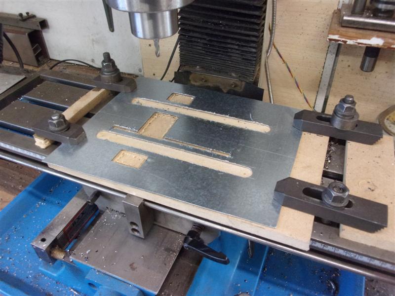
The ashpan has been made from 1.1mm galvanised steel sheet,
offcuts from the skip of a local engineering firm. It's a complex shape
and there is no pre-development length given on the drawing. The overall
length was calculated by scaling from the drawing using the side view. To
get started, a piece of material was marked out and set up on the mill to
clear away the material for the ashpan doors and the two tunnels over the
pony frame. 3mm drilled holes marked the start of machining. A 3/16" slot
drill was used to clear away the door openings and the tunnels were made
with increasing sizes of slot drill up to the final size of 16mm. There
is also an additional slot that the cylinder cock rod passes through. |
 |
 |
Because I don't have a bender / folding tool bending was
done between a pair of steel angles held in the vice. The slots for the
tunnels allowed a pair of engineers clamps to add additional support in
the middle. Offering the folded component up to the drawing showed my dimensions
to be reasonably correct. |
 |
 |
The tunnels were made next from some thinner material,
bending it around a 9/16" dia bar. These were offered up to the slots and
the shape scribed onto the material from the outside of the ashpan. Another
view of the completed tunnels. After I have burnt off all the paint and
cleaned them up, these will be silver-soldered into place. The galv will
also be removed: by chance, I discovered that the citric acid pickle also
disolves the zinc, something I wasn't previously aware of. |
 |
 |
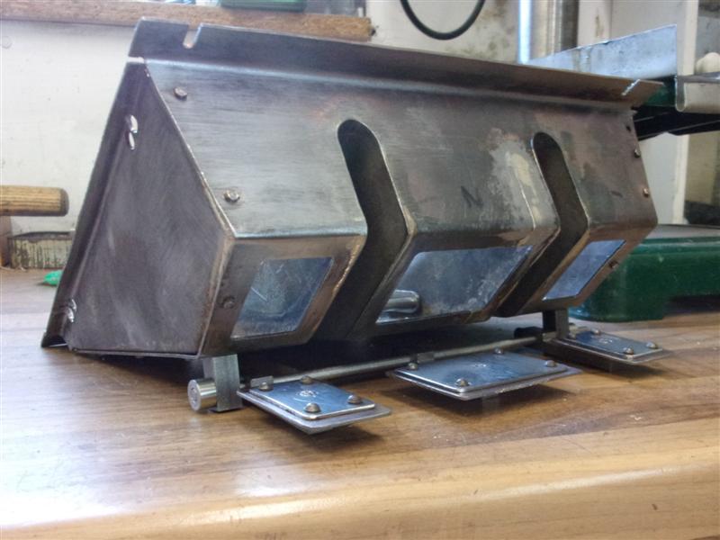
The outside edges of the ashpan were cut away next and
the side panels made to fit. This was a balancing act to get all the angle
to agree with each other and the linisher was used to nibble away at the
material until I was satisfied with the shape. This is the final shape of
the ashpan with the sides resting alongside. |
 |
 |
And this is a similar shot with the sides resting in place.
I'm not going to fix these just yet because, at present, there is no way
to replace a damaged fire grate without lifting the boiler, not that I can
see anyway. My tunnels are lower than shown on the drawing and I may be
able to do something by having a removable side. My grate will be the built-up
stainless steel variety, not the cast iron grate that is available. |
 |
 |
The next thing done was to create the seating for it on
the frames. I made a full-width support bar for the front from 1/2" x 3/16"
flat mild steel, and milled the top at an angle of nine degrees to match
the slope of the firebox. The rear support was made from two pieces of 5/16"
square bolted together, only because I had no 5/8" x 5/16". These sit on
the two support brackets which are already at the correct angle. Each bar
has a pair of 3/32" dia pins set in to locate the ashpan correctly and also
to allow the pan to expand a little if needed. |
 |
 |
The ashpan doors were made next as per drawing, along
with the support blocks and the operating rod. These were then fitted to
the two brackets on the side of the frames. Whoever designed that was an
idiot. The doors don't seal, are really difficult to adjust and ash will
get in the mechanism all the time. Norman N. sent me a picture of what he
has made and I have blantantly copied his design. Thanks, Norm. The mechanism
has been moved rearwards, the doors have an outer leaf to allow sealing
and new arms have been made to suit. |
 |
 |
Here is a picture of the new arrangement and, as can be
seen, I've also silver-soldered the tunnels to the ashpan and filled that
ridiculous slot for the cylinder cock operating lever. I will sort out something
different for that, maybe a bowden cable. In this final view, the doors
are closed and the operating lever can be seen to the side. Also on view
are the end of the grate-lifting mechanism and a modification to the side
of the ashpan. |
 |
| 2. Grate |
|
|
 |
The grate is made from 12mm x 3mm stainless steel flat
bar, supported on 5mm dia stainless steel rods and with 10mm dia spacers
between the firebars. The width of the spacers are different front-to-back
because of the firebox taper. The spacers were made first and, because there
are fifty seven of them, a simple stop and part-off arrangement was set
up to speed up production. I drilled about an inch deep and then parted
off four in each batch. After doing nineteen at 0.207" for the back row,
the stop was adjusted and the next row done. The variation in each batch
was no more than one thou. The bars were sawn to length, drilled to accept
the 5mm rods and assembled with 5mm st.st nuts on the ends. The centre section
drops, as per drawing, but I have moved the front tie bar for this further
forward to better support the firebars. I've had to use thin-headed screws
on the drop-down section, though, because the nutted rods were fouling the
sides of the ashpan tunnels. |
 |
| 3. Lower Clacks |
|
|
 |
The lower clacks are made from two parts silver-soldered
together. The body was turned from 1/2" dia brass, drilled 9/32" with a
flat-bottomed drill, finished through with a 3/16" drill and then tapped
5/16" x 40 tpi for a plug and then parted off to length. The opposite end
was turned to size and threaded 3/8" x 32 with a button die. A cross-hole
and spotface were formed in the side. The branch was made with 3/8" dia
material threaded 3/8" x 24 tpi most of the way, a spigot formed on the
back and then parted to length. This is similar to the top feeds. When I
soldered the top feeds together, I had one instance of solder getting where
it wasn't wanted and had to clean up. This time I painted the insides of
each clack body with correction fluid. |
 |
 |
A ring of solder was placed around the branch and the
assembly heated. A groove in the block helped keep it all upright. I only
needed two but made a couple of spares in case of sealing problems later.
I intend to use 1/4" dia silicon nitride balls in these. I also made some
thin locknuts instead of having the shoulders shown on the drawing. Much
easier to get them in line this way. Top plugs for each were also made,
same as for the top feeds. Here they are, cleaned up and ready to go. Again,
bronze would be a good choice of material here. |
 |
| 4. Blowdown Valve |
|
|
 |
I have modified the blowdown valve from what's drawn to
enable use of an Allen key instead of making a special tool. I will use
the same key that I use for the tender parking brake, a 4mm Tee-handle type.
The shut-off plug has been converted to a collar by drilling and tapping
it M5 and an M5 cap screw used. The rest of the valve is as-drawn and I
am using a silicon nitride ball to seal. The pipe joints are silver-soldered,
although the outlet side could be soft-soldered as there in no pressure
there. Also, I need to drill an additional hole in the right-hand main frame
to let the key through, something that the designer forgot to specify. |
 |
| 5. Superheater Elements |
|
|
 |
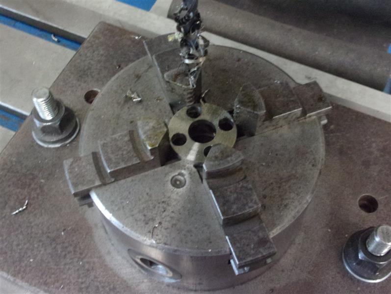
I am making radiant hairpin superheaters rather than what
is on the drawing and am using 6mm o/d x 1mm wall S316 stainless steel tube.
After cutting four pieces at 1260mm long for the hairpins, I made a simple
bending former. This is a piece of 1" dia mild steel, skimmed to 25mm and
with a groove 6mm wide and 13mm diameter at the lowest point. A piece of
offcut is resting in the groove to check the size. I couldn't be bothered
to make a bending handle and just formed the hairpins freehand around the
former. First, the tube was rested in the former at the half-way point and
clamped with an engineer's clamp. |
 |
 |
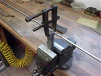
The two ends of the tube were then bent until they were
parallel. Next, they were slowly squashed into the former, using the vice
as a press, until the tails started to cross over. |
 |
 |
A piece of 13mm (well, 15mm actually, but 13mm would have
been ideal) flat bar was placed between the tails and the squeezing continued
until the tube was full in the former. This is how they look after the vice
is fully closed and the packing removed. |
 |
 |
They were then tapped fowrard with a hide hammer to release
them from the former. I found that the stainless tube bends very easily
and there is no visible distortion of the tube in the area of the bends.
And here are two of them sitting the wrong way round in the superheater
flues as a size check. I will be having two hairpins in each flue, held
in a cruciform arrangement. |
 |
 |
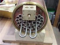
To keep the superheater elements spaced apart, I made
up four discs from some stainless steel bar, turned to 28mm diameter with
a 12mm hole drilled through and parted off about 3mm thick. Four holes were
then drilled on a 19mm PCD to maintain the designed 25mm outer form. These
were then tested for fit and to get an idea of the overall shape and size
of the element assemblies. |
 |
 |
I don't fancy the idea of silver-soldering stainless tube
so I have decided to screw some copper tails to the hairpins which will
be silver-soldered to the respective headers. With the tubes already bent,
it was easier to use my tailstock dieholder with a brass guide mounted in
the opposite end to ensure the die was perfectly square to the tube. I am
using a collet block to hold the tube to prevent damage. The thread I am
using is M6 x 0.75 for which I have both tap and die. The die is mounted
back-to-front to maintain the normal lead on the thread. The other tail
has already been threaded here. |
 |
 |
I originally planned to have the cruciforms in the flues
and milled away some of the o/d to allow the flue gasses to pass more easily
but colleagues on the forum I frequent suggested it was not a good idea.
So I have reduced the o/d to 27mm and used them to keep the hairpins aligned
at the firebox end only. The wet and dry headers will hold them at the other
end. Here is a shot of the hairpins projecting into the firebox. |
 |
 |
I've now made all the parts for the wet and dry headers
and it was time to solder all the parts together. First, thought, the stainless
steel hairpins had bronze tails screwed on really tight. To keep the elements
from dropping into the wet header tube, I covered an 8mm bolt with correction
fluid and set it through the tube. The two short pipes joining the header
to the regulator steam chest were also set in place and the whole lot silver-soldered. |
 |
 |
All the various other parts were soldered on at different
times, about ten heat-ups all told. I've been a bit generous with the solder
but early on I had one joint that didn't go well and had to go back for
a second try. This is the assemb.ly seen from the boiler side. And one more
picture with it temporarily fitted in place with the smokebox on. I am using
olive connections at the cylinder end of the joining pipes but flat connections
at the header end because it will be much easier to fit and seal. The small
nipple below the dry header is for the snifter pipe. |
 |
| 6. Steam Pipes, Snifter |
|
|
 |
Rather than try to bend a couple of awkward 3/8" diameter
copper pipes to join the dry header to the steam pipes, I've used standard
off-the-shelf fittings to achieve the required shape. All that was needed
for each pipe was a street elbow and a 45 degree bend with three short straight
sections to get the distances correct. The first problem, though, was that
the fit of the parts was too loose so I squashed the fittings down a little
using a collet. To ensure that the orientation stayed correct, I silver-soldered
each pipe in two stages. The first stage saw the bends joined to the distance
pieces and the end fittings, leaving the final join for later. This meant
I didn't need to have the nuts on the pipes at this time. |
 |
 |
For the second stage, the joining parts were well-fluxed
internally and the pipes then reassembled in the smokebox and tightened
up with all the fibre washers. The joint was given a squeeze with mole grips
to wedge them together and the who lot then dismantled. This way, the two
halves of each pipe stayed in the correct position and were silver-soldered
in the normal way. I have used flat couplings at both ends rather than an
olive at the steam pipe end. The fibre washer will seal just as well but
it makes dismantling so much easier. The snifter pipe is 1/8" copper
tube with nomal nipples silver-soldered to each end. |
 |
| 7. Next item... |
|
|
| |
|
|