| Drawing 8 - Cylinders &
Accessories |
| 1. Cylinders |
|
|
 |
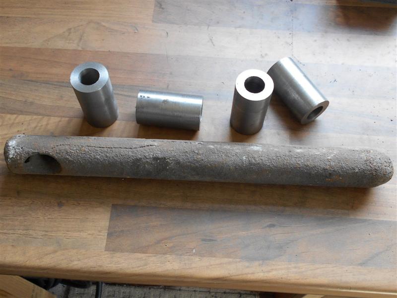
I have chosen to make my cylinders from the cast iron
casting that are available although I could have chosen gunmetal cylinder
castings or raw material of either type. I will also be using cast iron
pistons and cast iron rings. The castings were a reasonably good shape and
I didn't see any chilled spots although I wouldn't have expected to with
lumps this size, and with no small protuberances which are the usual casualties.
The first job I did was to load them to the independant four-jaw chuck on
the lathe and clean up the ends. If there were any chilled spots, my lathe
tooling is more substantial and better able to cut through them. I wasn't
trying to get anything accurate machined here, just to get a couple of flat
surfaces to help subsequent operations. |
 |
 |
They weren't coming off the lathe anything like square
so it was over to the milling machine and loading to an angle plate, getting
the casting reasonably square to the table and then cleaning these faces
up again. Again, I wasn't after anything accurate here, just a starting
point for clamping purposes. I used my large flycutter for this, 4" diameter
with a carbide cutting tip rotating at about 400 rpm. Once I was happy that
the ends were reasonably square, I then machined the back, clamping to the
angle plate through the two rough bores and removing enough material to
just clean up. These were now measured and checked properly for squareness
and centre-ing which showed there was still about an eighth of an inch still
to come off the length. To reduce the overall length, I opted to hold them
a little differently, using my independant 4-jaw chuck mounted to the table,
adjusting how much I took off each end to get them balanced. |
 |
 |
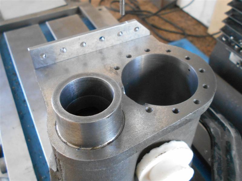
The drawing shows that the centrelines of the cylinder
and the valve bores are offset 7/16" from each other in the vertical plane
but a close look at the castings revealed that the core for the valve bore
is set about 1/16" too close to the front of the casting so I have made
the offset 1/2" which will allow the cylinder core to be machined reasonably
evenly and the valve core will lose 3/16" at the back and 1/16" at then
front to bring them back to the 7/16" offset. I set them up as shown below.
The plugs are small pieces of MDF wedged in and centered so that I could
eyeball the amount of tilt required. After setting the scribing block to
the centre of the valve bore, I set it on a piece of 1/2" tool steel and
adjusted the casting to set the centre of the cylinder. Then it was bolted
up, the clamp removed and the back faced off again until I had a full clean-up.
|
 |
 |
The next thing I did was to go back to the earlier ops
and get the overall length finished to size and to get the centreline of
the piston bore reasonably accurate to the back face. These were just repeats
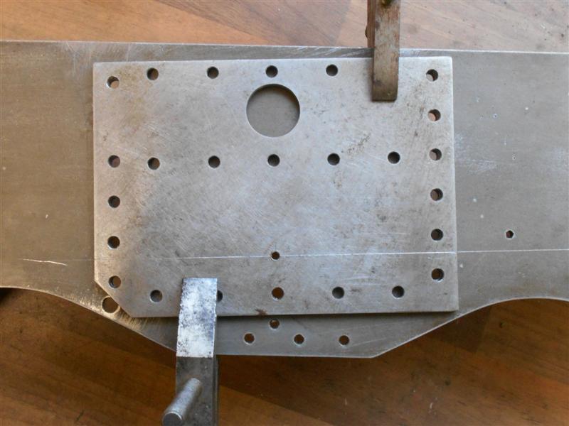
of the earlier machining. Then I drilled all the bolt holes on the back
of the cylinders but I've also added a couple of extra holes that are not
on the drawing. These have been reamed 3mm and I have also modified the
mounting plate by drilling and reaming two holes and setting 3mm dowels
into them. Although I am going to finish the bores using a between-centres
boring bar, it's a lot of work because these bores have a lot of meat in
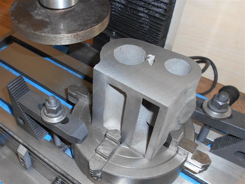
them. Therefore I set up to rough machine the two bores and had to make
a holder to carry the boring bar to enable me to load it to the 4-jaw independant
chuck. |
 |
 |
Here, I've loaded up the first cylinder and set the centre
of the bore before locking the slide in the first direction and taking the
gib screws up pretty tight in the other. Then it was just a case of feeding
through under power, backing out, adjust the bar and go again. However,
after the first few passes on the first cylinder, it became obvious that
the setup wasn't quite rigid enough so I stopped machining and modified
the lower clamp by bolting on a block with an M10 bolt through it. Once
I had clamped the cylinder up again, I then adjusted this bolt down onto
the slideway with just slight pressure and a piece of brass packing beneath
and this took practically all the spring out of the fixture. |
 |
 |
And this is where the dowels came in useful. I was able
to machine the largest bore on the first cylinder, unbolt it and load the
second cylinder and be confident that the two bores were in the same place
relative to the casting. Then l used the same boring bar to rough out the
valve bore before setting up for between-centres boring to finished size.
Because I put a pair of locating dowels in my mounting plate, I was able
to get everything clocked true and then load each cylinder in turn and continue
with between-centres boring getting each bore to about ten thou undersize
and then setting the boring bar to final size and finishing each bore in
turn. I have left all the bores three thou undersize to allow for honing,
which should be ample, but it won't matter if they need a bit more. The
valve liners and pistons will be made to suit. |
 |
 |
I was able to measure them in situ without removing the
boring bar using a dial caliper gauge but forgot to take a picture at the
time. Here is a picture taken later showing the type of clock I am referring
to. They are very good comparator gauges and I have modified this one slightly
with some pressed-on stainless steel feet. I set the size using a 1" - 2"
micrometer. To drill the various holes, I took full advantage of the new
DRO and used co-ordinate positioning throughout. Each cylinder casting was
squared up on the mill and the centre of the main bore accurately found
using a wobbler. Using the tables in the Zeus book for a twelve-hole setup,
I worked out the X and Y co-ordinates of each hole and worked my way round
centre-drilling and then drilling 3.0mm diameter. |
 |
 |
The draincock holes were also drilled and tapped 1/4"
x 40 and the final work on the mill was to mill the steam port and drill
and tap the holes. The drawing shows that the face of the steam port is
28.5° to the horizontal and recommends drilling the steam inlet hole
after assembly of the valve liners. Using angle gauges, I set mine to 27°
and milled the face flat with an endmill. I also drilled the 4BA stud holes
and the 5/16" dia steam hole at this stage and will drill through again
after assembly. The cast pads were not exactly in the centre of the castings
which is down to me for not getting equal amounts off of each end of the
casting. However, I have made sure that the holes are central to the end
faces. Finally, all seventy-eight holes were tapped freehand using a 4BA
spiral point tap (except the draincock holes, of course) and I am relieved
that all went well. To break a tap at the last moment would be disappointing
to say the least. |
 |
 |
Before I fit the valve sleeves, I needed to hone the cylinder
bores because access may have been a bit limited later. The hone kit came
from Cromwell Tools and did the job perfectly. If you've never used a hone
before, the trick is to start AND stop with the stones in the bore (never
pull the hone out whilst under power or you will probably destroy the hone),
and run at high speed for twenty seconds or so, stop, clean both the bore
and the stones, another squirt of light oil ( I used 3-in-1) and repeat.
Follow this routine until you're happy with the finish. As regards size,
you will probably need to work for half an hour or so to remove about three
thou in cast iron. It's all about surface finish, not removal of material,
get your size nearly correct before honing. |
 |
| 2. Cylinder Backplates |
|
|
| I cut the cylinder backplates out a while
ago using some 10 swg mild steel plate, offcuts of the frames material,
and had marked out and drilled them. I have now countersunk the holes and
screwed a few of the 4BA screws into place but one or two of the holes are
not as accurate as I would have liked. These were made before I had co-ordinate
drilling facilities whereas the cylinders were drilled using the DRO. I've
opened the lower row of holes out an extra four thou and the screws are
now pulling in, but I may remake these plates as there is not a lot of work
involved. One advantage would be that I can get the dowel holes that I have
added to the cylinder in the correct place. |
 |
| 3. Valve Sleeves |
|
|
 |
I am making most of the parts for the cylinders
from cast iron and I have now made the piston valve sleeves from some old
sash weights. The material is not of the best quality and I got black as
a coalman whilst machining it but the end product is quite acceptable. Unlike
the majority of components in this build, both the bore and the O/D need
to be very accurate and perfectly concentric because of how they are assembled.
This would usually lend itself to making from bar stock, machining both
the O/D and the bore to size and parting off to length as a single setup.
However, my lathe is not the most accurate machine in the world and that
is why I chose to do the job this way instead. The first job was to cut
up and rough out the four billets, although they were faced to finished
length at this stage. |
 |
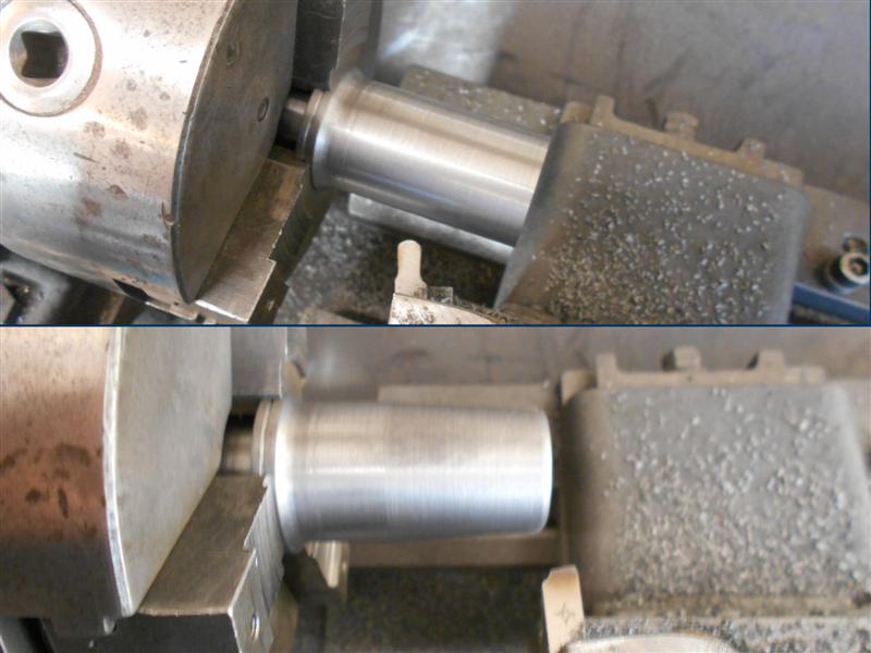
Next I modified one of my between-centres boring bars
to get down to this smaller diameter and also made up some brackets to hold
one of my machine vices on the home-made vertical slide. Although a lot
of time has been spent in preparing this, the vice arrangement will come
in useful again in the future, I am sure. All four sleeves were finished
in multiple passes and, therefore, marked with a felt-tip pen to ensure
they went back in the same place each time. To machine the outside, a mandrel
was made from some spare material and the sleeves loaded in turn and brought
to final diameter in multiple passes, the final cut being about six thou.
They were then reloaded to machine the slightly reduced diameter of the
external part of the sleeve, and for the steam port groove in each one. |
 |
 |
The last operation in the lathe was to load to the 4-jaw
and clock the bore true prior to opening out the locating spigot (0.950"
dia) for the end covers. Finally, it was over to the mill and the steam
port holes all put in. The inlet holes are just a series of eight drilled
holes of 3/16" diameter and the outlet hole a 9/32" x 9/16" slot. These
will now be cleaned up, pressed into the cylinders making sure the outlet
ports line up with the cast-in holes and the hone ran through each to get
a perfect central join. The piston valves will then be made to suit whatever
the final size turns out to be. |
 |
 |
I decided to take the cylinders to a local garage and
make use of their 30 ton press to push the four valve liners into place.
The liners protrude from the main casting by 0.712" at each end and a ring
of this thickness and with a biggish bore was made to rest the cylinder
on and act as a depth stop. A packer with spigot was also made to place
inside the liner to protect the liner from damage. The first one was aligned
with the cast-in exhaust ports of the cylinder and pressed in to just past
the finished depth. The assembly was then upended and placed on the depth-stop
ring the second one likewise aligned and pressed home until it touched the
other liner. A bit of extra pressure then moved both to the correct depth.
This was repeated for the other cylinder and the whole job took no more
than ten minutes. |
 |
 |
Now I needed to mount them to their backplates and get
them located on the frames for spotting through. The cylinders on Britannia
are inclined and it is not very easy to use co-ordinate drilling to mark
the holes in the frames. The other problem is that, because the cylinders
are castings, the centreline of the cylinders won't neccessarily be where
I think they should be. On the frames, I had previously marked out the position
of where the exact centre of the cylinder should be and scribed a line from
a given dimension at the front of the frames to the axle centrline of the
driving axle. |
| All I needed to to do was find the exact centre
of each cylinder and transfer this to the cylinder backplate and I could
then line everything up, clamp together and drill through. First I set up
an angle plate on the mill, accurately squared off, and mounted the first
cylinder and backplate assembly. Using a wobbler, I found the exact centre
of the bore then swapped the wobbler for a scribing point and, without moving
the "Y" axis, dragged it across the edge of the backplate. The assembly
was then upended and the procedure repeated so that I had a scribed line
at each end of the backplate. |
 |
 |
The backplates were then removed and a line scribed on
the plates between each of the two marks. Using a digital caliper, the half-way
point was marked, followed by centre-punching and drilling 3/32". Back with
the frames, I also drilled the previously marked cylinder centre point with
the same 3/32" drill. The plate was then laid on the frame. a 3/32" rivet
dropped through the holes and the marks on the end of the plates aligned
with the scribed line on the frames. The whole lot was then clamped together
and all the holes drilled through with a 4BA clearance drill. Clamping the
two frames together and doing as a single item wouldn't work because the
other cylinder alignment would probably be slightly different so he other
frame was machined separately and finished the same way. I also scribed
the position of the steam exhaust hole on the frames and these, along with
a few other holes such as the saddle mounting holes will also be completed
while I have the frames disassembled. |
 |
| 4. Rear Valve Guides |
|
|
 |
The rear valve guides are usually machined from gunmetal
castings but I decided to make mine from a couple of billets of cast iron
which are 40mm dia Meehanite and 75mm long. The drawing is not dimensioned
around the rib area and I have had to scale from the drawing to get the
sizes somewhere near. The first part of the job was to turn the O/D and
the front boss that fits in the valve sleeve. The hole for the valve stem
was also drilled and then bored with a tiny boring bar to ensure concentricity.
It chattered like a cage full of monkeys but finishing with a 7/32" reamer
cleaned it up nicely, These were then loaded to soft jaws to machine the
outer form of the guide rails and face to length. |
 |
 |
Next it was over to the mill to make the final shape of
the ribs. This entailed multiple operations, starting with hacksawing a
large lump from the front. The 4-jaw chuck was mounted sideways using an
angle plate and the centreline clocked and set on the DRO with all y-axis
dimensions were referenced from this. A 12mm endmill was used to get the
majority of the front-end material removed and a rummage in the "specials"
box came up with this cutter to produce the angled form using multiple cuts
and sneaking up on the shape until reasonably smooth. |
 |
 |
Now that there was some working room, the holes for mounting
the guide rails were next, drilling for 8BA. These will be tapped by hand
later. Because of restricted access up near the chuck, removing the waste
from the centre section meant making a holder to extend the reach of a 6mm
end mill. The holder is a piece of 5/8" dia bar reamed 6mm, then cross-drilled
and tapped M4 for a clamping grub screw. There was a small amount of chatter
but easily dressed out with sanding drums in the dremmel. |
 |
 |
The outside form was also machined with the same tool.
Most of these cuts for both operations were plunge cuts, moving over about
forty thou per cut and finishing with a ten thou facing cut to lose the
plunge lines. That is as much as can be done for now. They need to go back
in the lathe to machine the pocket for the valve gland and they will need
some relieving under the guide rails to clear the slidebar casting but I
will leave this until assembly time. |
 |
| 5. Valve Guide Glands |
|
|
 |
Tthe valve glands have been made from bronze bar and this
was just straightforward turning and parting off followed by loading to
the 4-jaw on the mill and drilling the 8BA clearance holes. I then marked
out the shape of the flange and the edges were hacksawed off and linished
smooth. I have also now put the tapped holes and the pocket in the valve
guide and this needed a couple of extended tools made to reach. The drill
is jammed into a short length of brass tube but not soldered, remaining
tight during the drilling of the four holes. I didn't have any tube suitable
for the 8BA tap so I drilled a hole in the end of 1/8" key steel and banged
that onto the end of the tap, which saved having to file some flats for
the tap wrench. |
 |
 |
The pocket was created using a 10mm long-series slot drill
since I didn't have a 3/8" one and the gland turned to suit. These were
then assembled but without the PTFE washer and it became apparent that I
had an alignment issue. It wasn't much but enough to stop a 7/32" turned
rod from sliding through, even when I loosened or turned the glands through
one-eighty degrees. I must have messed up on my clocking up somewhere. I
decided that the best thing to do was to increase the size through the gland
and valve guide to the next standard size. 7/32" is approximately 5.5mm
so I decided to lift that to 6mm, the advantage being that 6mm dia stainless
rod is easily available as a stock size |
 |
 |
The soft jaws were returned to the lathe and re-skimmed
- the chuck had been off in the interim - and the guides and glands were
assembled and marked as pairs, complete with orientation, just in case I
have to disassemble them again. A special boring bar had to be made but
this will come in useful for other things in the future so worth the investment
in time. The home-made boring bar is a piece of silver steel which I have
hardened and tempered. The assemblies were then loaded to the soft jaws
and a few passes made taking three or four thou at a time until I could
get the shank of a 5.7mm drill in the hole. This was enough to true them
up and then the 6mm reamer was pushed through. |
 |
| 6. Front End Caps |
|
|
 |
The front caps for the cylinders have been machined from
blanks sawn from bronze plate using offcuts from the smokebox door and ring.
I started by marking a circle on them using a cardboard disc and felt-tip
pen, then aligning the rough billets in the independant 4-jaw chuck. These
were then faced off and the outer diameter turned to size, a small radius
being filed on also. The opposite side was turned using soft jaws in the
3-jaw chuck. Care was taken to ensure an accurate size for location in the
bore, and good finish on the cylinder mating face although a gasket could
be used if neccessary. |
 |
 |
The spigot depth was controlled to exact size using the
compound slide to set the tool. The bolt holes were produced on the mill
using the DRO and the data from the Zeus book. The self-centering 4-jaw
chuck was mounted on the mill table and the first workpiece accurately centered.
The covers use a twelve-hole solution but with only eleven used because
of the cutaway on the reverse to allow steam in and out of the cylinder.
After finding the position of the first hole, this was marked with a felt-tip
pen and NOT drilled. It's too easy to forget ones self and mess it up at
this stage by drilling twelve holes. |
 |
 |
Each of the rest were centre-drilled, drilled and countersunk
at each of the positions alternately. It's a little laborious keep changing
tools but no more so than winding back and forth three lots of times. Before
removing from the chuck, a 6BA blind hole was drilled and tapped at the
0,0 co-ordinate for fixing the outer cover to, and the cylinder end cap
is not seen once all is assembled. Finally, the steam access cutaway was
machined by holding vertically in a vice and using a woodruff cutter to
create the recess. By finding the centre of the workpiece and loading on
two drills, the cutaway has to end up in the correct place. I only had a
1/16" wide cutter so four plunges were taken in forty five thou steps to
create a 3/16" high recess. |
 |
| 7. Rear End Caps |
|
|
 |
I have made the rear cylinder caps from cast iron although
the glands are from broze offcuts. I made the glands first because I wanted
to fit them to the cylinder caps before final sizing. The bore is just pilot-drilled
at 1/4" diameter in the photo. To make the cylinder cap, I started by turning
the O/D and forming the locating spigot for the cylinder bore, leaving it
twenty thou above finish size. A 1/4" pilot hole was drilled through the
billet as well. |
 |
 |
They were then loaded to soft jaws and the second operation
undertaken. It seemed a shame to waste so much cast iron machining the gland
housing so I removed a ring of material using a hole saw to create a radial
groove in the face and then parted the ring off. These will come in useful
for something one day. The rest of the machining was then completed, ensuring
that the gland was a good fit in the housing. Moving over to the mill, all
the holes were drilled on their respective PCD's in a similar fashion to
the front caps (covered earlier) and the gland fixing holes tapped 8BA. |
 |
 |
8BA studs were then fitted to the end caps and the glands
inserted and nutted down tight. The assemblies were then returned to the
lathe, held in soft jaws, and the piston rod holes bored and reamed to size.
The cylinder locating spigot was also skimmed to final diameter, plus a
couple of thou of the face, which ensures that the whole assembly is perfectly
concentric with the bore of the cylinder. Finally, the steam inlet recess
was formed in the same manner as the cylinder front caps. The underside
of the glands and the housings have been notched to aid correct repositioning.
A piece of 3/8" dia centreless ground material has been set in place to
check the fit. |
 |
| 8. Valve Front Cover |
|
|
 |
I have made the valve front covers from cast iron, in
this case from some old but better-quality sash weights. I machined the
O/D and the spigot for the valve first, and drilled the valve rod guide
hole to depth at the same visit. The parts were then reversed in the chuck
and the rest of the machining completed as a single operation. |
 |
| 9. Pistons |
|
|
 |
The pistons have been made from cast iron billets, whilst
the piston rods are made from an unknown grade of stainless steel and I
am using two cast iron piston rings rather than the single "O" ring specified
on the drawing. I started by cleaning up one face and the O/D of the billets,
then prepared some soft jaws for subsequent operations. The O/D was left
thirty thou up for finishing after assembly but the bore and thread were
finished to size at this visit. My billets were just over an inch long and
I was able to get a piston ring from each one but I missed a trick by not
ordering slightly longer billets to enable two or more rings to be made
from the surplus. These were made first, then the piston body was faced
to length. |
 |
 |
This was followed with the piston rods, machining to finished
length and forming the thread. Because I only have one 5/16" x 40tpi button
die in carbon steel, I didn't want to risk it with stainless steel so looked
for an alternative. I have got a HSS M8 x 1.0 die, though, and it was cheaper
to use this and buy a matching tap for the piston body. The rods were screwed
into the bodies and pulled up really tight. The assembly was returned to
the lathe and set up between centres prior to finishing the outside diameter
to 1.749", and the two ring grooves formed. I have made these 1/8" wide
by just over 1/16" deep since this seems to be a standard size. |
 |
 |
Returning to the rings, the soft jaws were remachined
to the new diameter and the billets reversed in the chuck. The front ends
were skimmed to true the face, the inside bored out to 1.625" and the O/D
finished at 1.750". The rings were parted off at 0.125" wide. Two more rings
were made from raw stock and all four were then carefully broken at a single
point by holding in the vice and being given a sharp tap from a hammer and
punch. The inner faces were filed smooth and square to help the next part
of the job. |
 |
 |
Next they had to be expanded for an easy fit over the
piston and to give a spring contact to the bore of the cylinder. They were
sprung onto a length of 3/16" thick flat stock and heated until cherry red,
at which point they dropped off the flat stock and were left to cool. After
a light clean-up with some wire wool, they are ready for assembly onto the
pistons. |
 |
| 10. Valve Spindles |
|
|
 |
Because I had to enlarge the hole through the valve guide,
I have made my valve spindles from 6mm dia stainless steel with a M5 thread
at the slidebar end and using M6 x 0.75 for the bobbin locking screws rather
than the specified 7/32" x 40 tpi. The drawing incorrectly suggests using
2BA nuts on these threads. The central area has been reduced to 5mm to ensure
it clears the root of the thread. I also drilled a 5/16" dia hole through
my button-die holder mandrel to allow the spindle to pass further through
the die-holder. The nuts were made from some 3/8" hexagon brass and used
as a gauge to set the size of the male thread. |
 |
| 11. Valve Bobbins |
|
|
 |
The valve bobbins are made of cast iron to match the valve
liners although the drawing calls for stainless steel if using gunmetal
liners. I made both bobbins from the same stick of meehanite using the centre
section for holding in the chuck. I started by cleaning up the front face
and roughing out the O/D to thirty thou oversize. Next I machined the centre
reccess to finish diameter and accurately finished the front shoulder dimension
to 0.312" and the gap to 1.375" with a wide parting tool . Because I am
using 6mm for the valve spindles, rather than 7/32", I then drilled and
reamed the through-hole at 1/4" diameter. After turning round and repeating
for the opposite end, I then parted off the two valves a few thou over-length
and finally faced them to exactly 2.000". |
 |
 |
A 1/4" diameter mandrel was made and left in the chuck
to ensure concentricity and each bobbin loaded in turn. The O/D was then
slowly reduced until just a couple of thou above finished size and then
slowly polished down with an abrasive block until they were just starting
to go in the valve bore. Then I used the hone in each bore, polishing until
I had a slightly stiff, sliding fit. Each bobbin was matched to it's respective
cylinder and marked to ensure they didn't get mixed up. The two bores are
about half a thou different to each other. They have been loaded to their
respective rods and will be adjusted for position at the appropriate time. |
 |
| 12. Cylinder Cladding |
|
|
 |
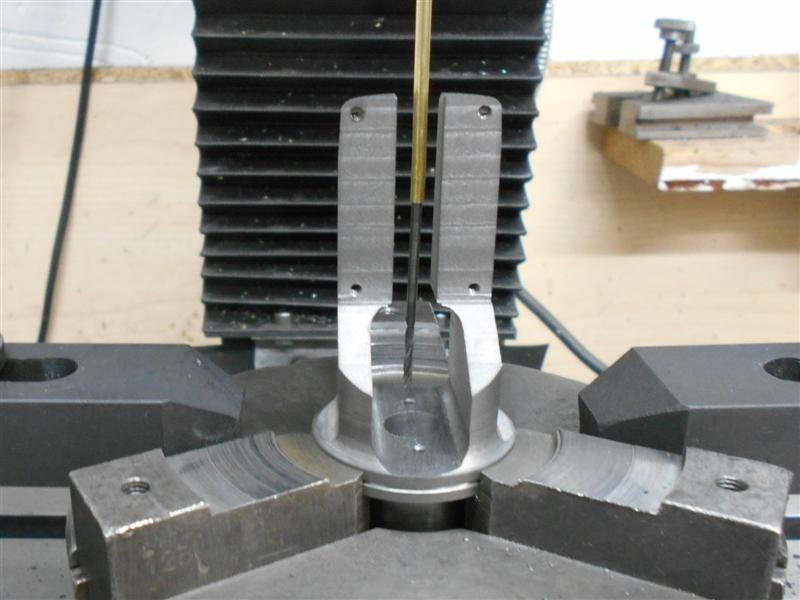
I've been playing around with the cylinder cladding and
am using the same number of fixing points as the prototype. The drawing
calls for 22 swg brass or copper sheet but I'm using 28 swg (eighteen thou)
because it doesn't look so bulky. First, I marked out the cutaway for the
steam pipe and flange, leaving some material to make into tabs. I've clamped
the two pieces onto some 12mm MDF and am using a 1/8" cutter to remove the
waste. Once that was complete, I reclamped the job and drilled the various
rivet holes, 1/16" for the fixing rivets and 3/64" for the inspection cover-plate,
or whatever it is. |
 |
 |
The positions of the rivets were guessed with reference
to a photo I took at Bressingham twenty years ago. The larger holes are
for the cylinder cocks. One can see where I'm attempting to make the tabs
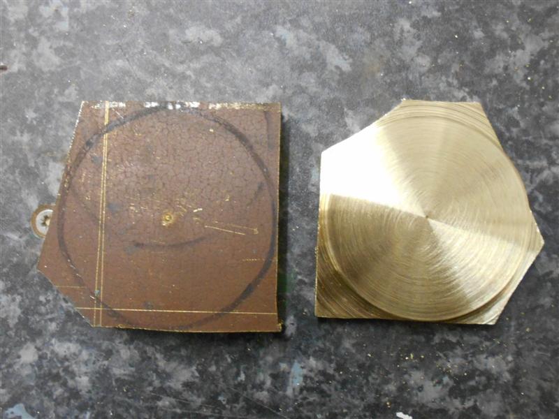
to support the steampipe cover part of the cladding. To make a perfect circle
in thin material is not easy and I chose to screw a pair of blanks to a
block of roof batten and set it in the rotary table. I only had to find
the centre of rotation - centre of the chuck - and not worry about the postion
of the material. |
 |
 |
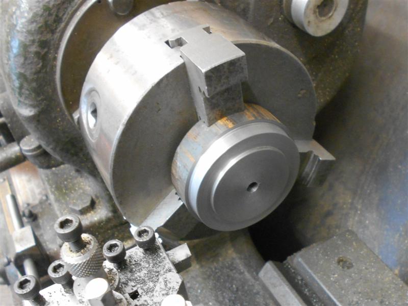
After drilling the four 1.2mm holes on a 3/4" PCD, I then
loaded the 1/8" slot drill and wound out to 0.531" on the "Y", 0 on the
"X" axis. After plunging through, I was then able to wind the table round
to create the 15/16" diameter circle needed. After getting about half-way
round, I added a couple more screws and washers to hold the discs firm.
I then returned to datum, set the cutter down to depth and finished the
cut. The photo to the right is the fireman's side and clearly shows the
rearward offset of the circular cover plate. |
 |
| 13. Cylinder Drain Cocks |
|
 |
The cylinder drain cocks are made from 5/16" square brass
bar and look nothing like the prototype. These were made on the lathe using
the 4-jaw self-centering chuck and are quite straightforward items. I screwed
mine into place and numbered each one to ensure they go back in the same
place. Once tightened up, the side face was marked prior to drilling and
reaming 5/32". The pins were made from 5/32" stainless steel using a drill
jig to drill the three holes or two holes respectively. The stock bar was
drilled first, then parted off to length. |
 |
 |
The linking rods were made from 16 swg brass strips, and
using the DRO to get the hole positions. I have used 3/32" diameter iron
rivets which I have threaded 8BA to act as link pins and the discharge pipes
are made from offcuts of 3/32" brass tube. I cheated and bought the olives
and union nuts, they are not worth making, in my opinion. Assembled it doesn't
look much like the prototype but once it is all painted black, it probably
won't show. I will leave the pipes shiny, of course. |
 |
| 14. Cylinder End Covers |
|
|
 |
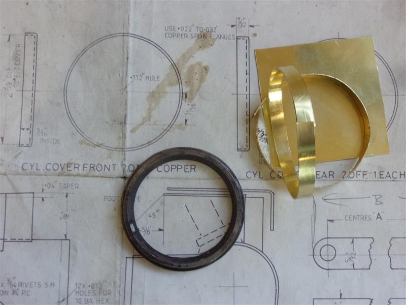
The drawing suggests making these from thin
copper sheet and spinning the flanges. I've not had great success with spinning
so, following the ease of making the mudhole covers, I decided to adopt
the same procedure. I have used 24 swg brass sheet because I have a reasonable
quantity of it in stock. They need to have at least 3/16" depth inside the
cover so I cut four strips 1/4" wide by 7.9/16" long, four plates 2.9/16"
square and made a former to clamp the strips around. The diameter of the
former is 2.3/8", the same as the cylinder end caps, and is 5/32" long with
a locating shoulder at 2.1/2" diameter. The middle is bored away and tapered
to help see what's going on when soldering. |
 |
The first strip was wrapped around the former and trimmed
to length, the ends just butting up to each other, and a wire tie wrapped
round to hold it firm. The bottom was then dressed on emery paper to give
full contact when on the brass plate. Flux was applied in a circle on the
plate and the ring rested on top. Sections of solder were rested against
the ring, some inside and some outside. I tried resting the workpiece on
two blocks and heating from beneath but this failed dismally when the thin
plate sagged in the middle. So, for my next effort, I just laid the assembly
on an ash block and used a lump of flat bar to hold it down. |
 |
 |
So this is what I ended up with. Because the ring is only
5/32" deep, there is a large enough gap at the bottom to stop the ring being
soldered to the workpiece, which can be prised out once the wire wrap is
removed. The corners were cut off and the outer shape dressed on the linisher,
followed by a good polish with abrasive blocks and emery cloth. Most of
this was done by putting the workpiece back onto the former and holding
in the lathe. I chose to use soft jaws to minimize the chance of distorting
the work. The penultimate job on the lathe was to dress the covers to length.
For this, I added extra support with a centre and plate, then plunged to
depth with the racking handle. Facing off in the usual manner would likely
have deformed the thin section. |
 |
 |
For the final lathe job, the two covers for the rear of
the cylinders had the centre bored to 13/16" diameter to clear the piston
gland housing. Then the chuck was removed and remounted on the mill so that
the various holes could be drilled. The loco is upside-down on the bench
at the moment with one cover in place. The front ones are a nice spring-fit
on the end plates so I decided not to drill the 6BA fixing hole on these.
These should be a silver colour so I will look into what can be done, maybe
satin-chrome of somerthing. If anyone else follows this procedure, I would
recommend using a thicker gauge of brass sheet. This 24 swg material is
quite flimsy and the few thou extra thickness of 22 swg would make a lot
of difference. |
 |
| 15. Next item... |
|
|
| |
|
|