| |
My Workshop |
|
 |
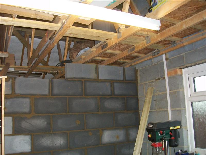
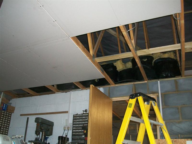
My workshop is one half of a double garage that I built
during 2012. The following year, I started to internally partition the garage
to give me a dedicated workshop space and during April 2015 completed the
partitioning of the space, followed by putting up a ceiling. This meant
that I could insulate above my workshop and keep it a bit warmer in the
winter months. I was finding in earlier years that everything was getting
covered with a fine patina of rust by the spring and I would then have to
spend a lot of valuable time just de-rusting everything. Prior to putting
in the ceiling, heating would have been impracticable as it would just rise
to the apex of the garage, the only beneficiaries being the pigeons who
perch on the ridge tiles. |
 |
 |
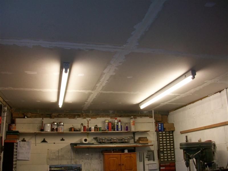
The workshop is built with a brick outer skin lined internally
with Celcon-style blocks and has a concrete floor which measures 5.5 metres
by 2.95 metres. The garage door is just a dummy and is faced with 60mm dense
polyurethane foam (Celotex / Kingspan etc) while the main entrance door
and window are modern double-glazed units. Power comes up via a 6mm steel
wire armoured cable and the garage has it's own earth rod but there are
no other services connected. Lighting for the area is by four flourescent
tubes independantly switched left-side and right-side and there are ten
double sockets around the workshop as well as a separate circuit for the
lathe. |
 |
 |
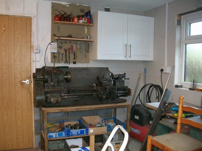
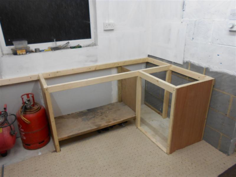
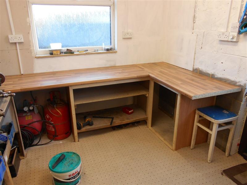
The workbenches are all homemade from 60mm x 35mm scant timber with a
mishmash of second-hand kitchen worktops set at my favoured working height
of 900mm (3 ft). All the small machines are screwed or bolted directly
to the worktop except for the lathe which is on a sturdy angle-iron frame.
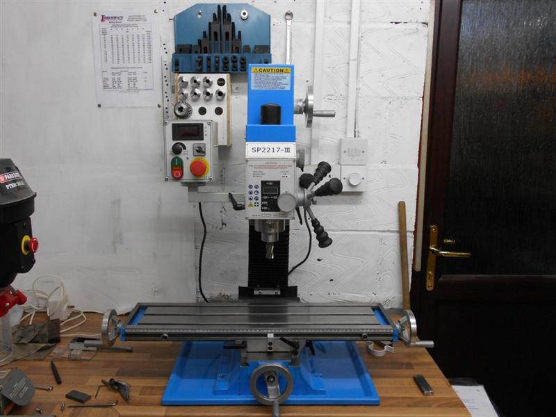
12/12/15 - I have now rearranged the window end of the workshop and built
a new bench to accomodate the new mill. I have made this bench 100mm lower
than the other benches so that working the mill is more comfortable. |
 |
| My Machinery |
|
|
 |
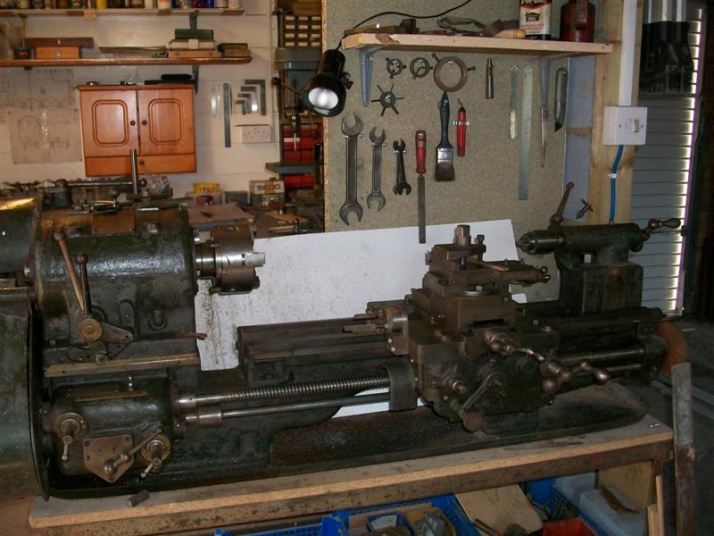
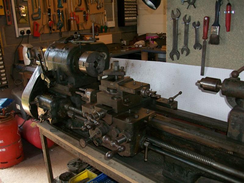
My lathe is a Keighly Lifts lathe which is a wartime clone
of the Denham Junior and has the war department crows foot embossed on the
end of the bedway. There are six speeds available and, because I have altered
the driving pulley, the range is approx. 60rpm to 1200rpm. It can swing
7.1/2 " dia over the saddle, 11.1/2" dia over the bedway and an
impressive 17.1/2" in the gap if the gap-piece is removed. Distance
between centres is 28" and the tailstock barrel has 3" of movement.
It has feed to both axis, although not simultaneously, and also screwcutting
selected by change-wheels at the end and a 3-speed gearbox selector at the
front. The spindle is threaded 1.3/4" x 6 tpi with a 1.750" register
and has 13/16" clearance through and a 3MT taper to the nose. The spindle
is clutch-driven and, for obvious reasons, is single direction only. |
 |
 |
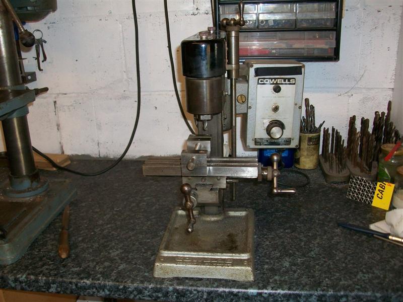
My milling machine is an early Cowells, built in Norwich,
and is smaller than the current version which has an extra 50mm under the
head and longer table. The machine is calibrated in metric and the largest
collet available is 10mm so not really ideal for a 5"gauge locomotive
but I inherited it from my father and have used it extensively since. When
funds allow, I intend to purchase a new mill and will choose one with a
600mm to 700mm long table. |
 |
 |
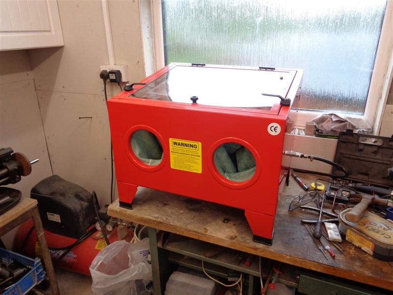
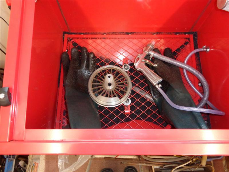
I have a couple of drilling machines, neither of which
are much good, and a combination small belt linisher and grinder. More recently,
I purchased a small shotblast cabinet to help with cleaning up materials
and have been well pleased with it. The photo to the right shows one of
Britannias coupled wheels inside the cabinet, so plenty of room. |
 |
 |
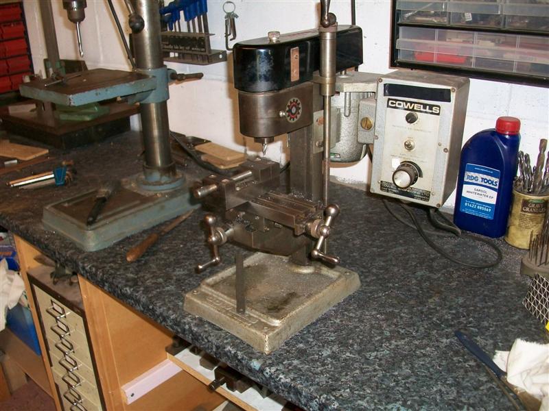
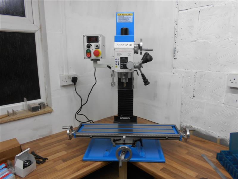
In December 2015 I purchased a new milling machine to
give me enhanced facilities. I have a number of items that I wish to make
but would struggle with my little Cowells mill, However, I'm not going to
part with the Cowells any time soon as it is a sturdy little machine and
extremely accurate. The new mill is equivalent to a Warco WM16 but with
an R8 spindle instead of 2MT. The main advantage of this is that milling
cutters can be held in collets extremely close to the spindle nose with
additional height now available. The only disadvantage is that 2MT tooling
has to be held in an adapter with a subsequent decrease in height available
but, for me, this is no problem. |
 |
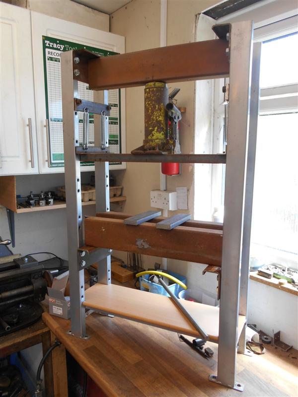
| Although I've used the hydraulic press at
my local garage, I fancied making my own so that I don't have to keep driving
up to Cowes each time I need a bearing pressing in or out, or loco wheels
pressed onto axles. What spurred me on was the need to replace the front
wheel bearings on my van and being quoted about £ 180 each to do them. The
bearings are £ 18.50 including VAT at my local motor spares shop so well
worth making the effort to build the press. Getting the bearings out and
back in will need some serious effort. A couple of years back, I scrounged
a couple of long lengths of 4" x 2" box section with 5/32" wall and this
came in very useful for this project. It has some real strength and well
able to handle any pressure I'm likely to throw at it. The side legs came
from an old bed frame that has been stored at the back of the garage, and
I dug out my old 5-ton bottle jack from the murky depths. Although five
tons is it's safe working load, in this application it will go to fifteeen
tons easily. The only parts I've had to buy were some M10 high tensile bolts
and four heavy-duty springs from the local hardware store, total outlay
about £ 12.00. This took me a good part of the weekend to build (amongst
garden duties and other distractions) but I'm well pleased with the result. |
 |
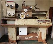 |
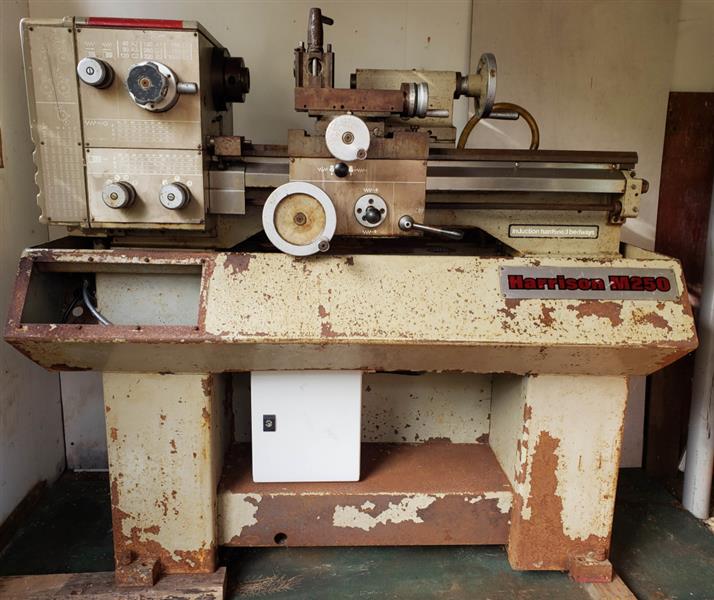
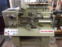
I puchased the machine on the left back in Autumn 2023
and spent the winter refurbishing it, finishing with the machine on the
right. It's 3-phase, powered by an inverter and calibrated in metric. It
also has flood coolant and is now used more frequently than my old lathe. |
 |