| 1. Intoduction |
|
|
 |
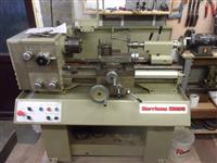
During a chat round the "Engineers Table" at
the Isle of Wight Model Engineers Society one Wednesday, I learnt that the
widow of a recently-deceased member of the club was selling the contents
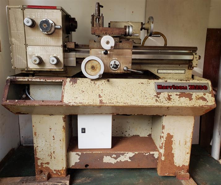
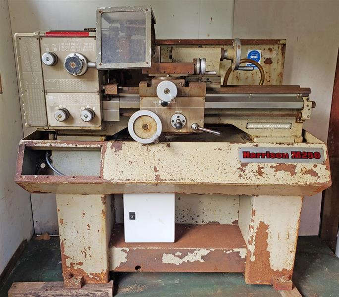
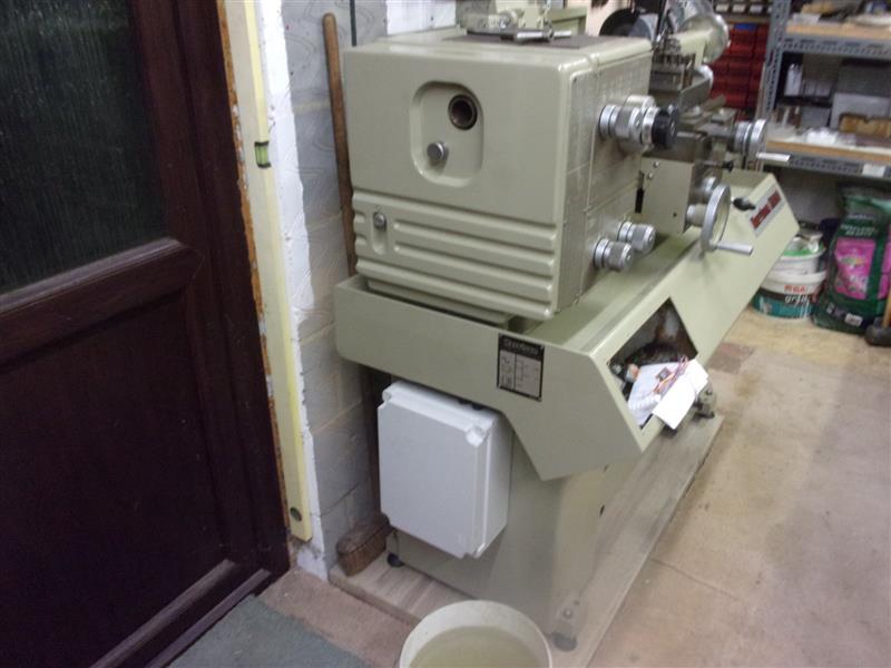
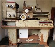
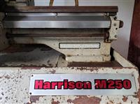
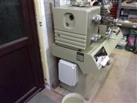
of his workshop, in particular a Harrison M250 lathe.. I arranged to go
along and view the lathe and, to be honest, it looked about ready for the
scrappy. It had been kept in a damp, wooden shed at the bottom of the garden
and was covered in rust. |
 |
 |
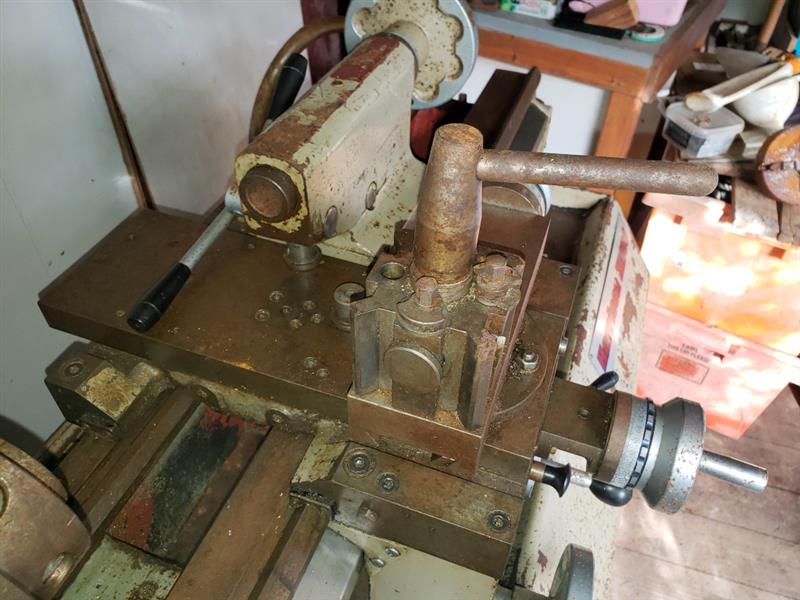
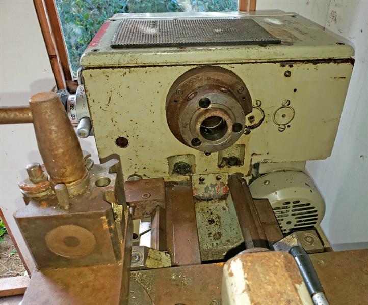
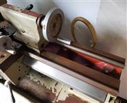
The cross-slide moved but not the carriage and the headstock
rotated - just! The owner had been planning on restoring the lathe but never
got around to it. Because of it's poor state, it had been advertised on
Tony's Lathes for £450. I made an offer on the complete contents of
the workshop, whch was accepted, and then the problem of how to move everything
had to be solved. The lathe alone was about 600Kg and there was no obvious
way to get it up the garden over waterlogged grass and down a set of four
steps to the road. |
 |
 |
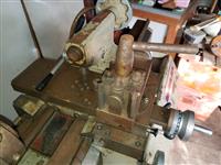
In the end, it came down to stripping the lathe down to
it's various components and transportting the items separately back to my
own workshop. The tailstock was removed first, followed by the headstock,
then the leadscrew and feed shaft. These had to be removed to free the apron
gearbox, the cross-slide and the saddle itself. Next the screwcutting gearbox
was removed. Even with all this off, it was still too heavy for two guys
to shift so the bed was, with some difficulty, separated from the base.
The coolant tank and motor were also removed as were any other bits that
would lighten the load. |
 |
 |
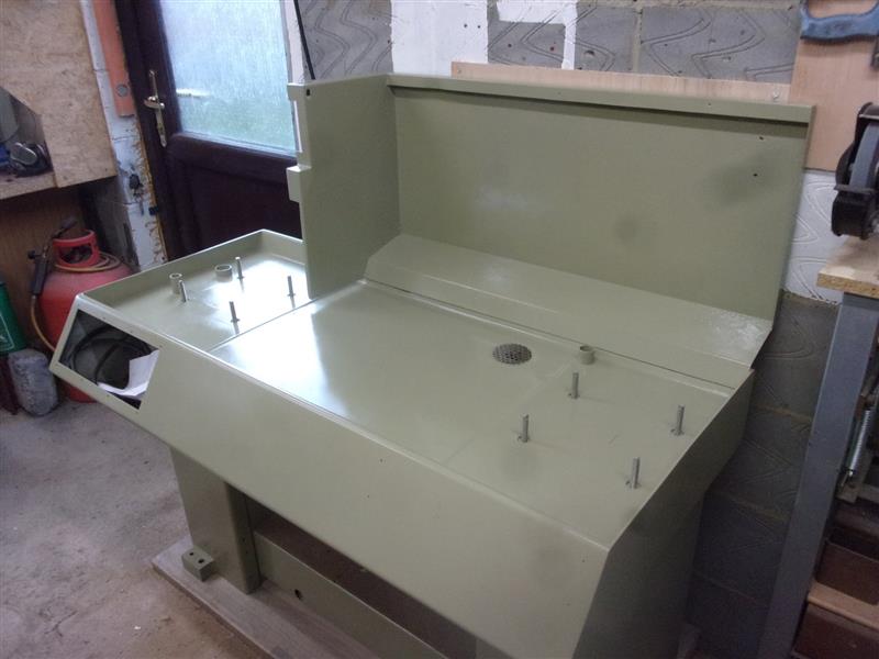
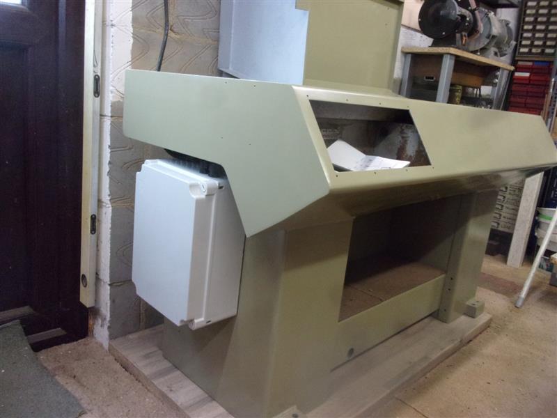
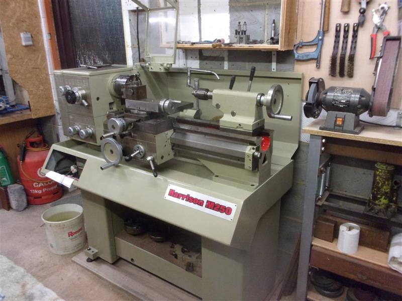
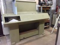
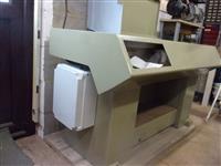
Over the next couple of months all the parts were thoroughly
cleaned and de-rusted, then given a couple of coats of enamel paint. A kitchen
worktop base was prepared in the chosen position and the process of rebuilding
the lathe started by getting the stand into place and the coolant tank refitted,
along with the rear guard. |
 |
 |
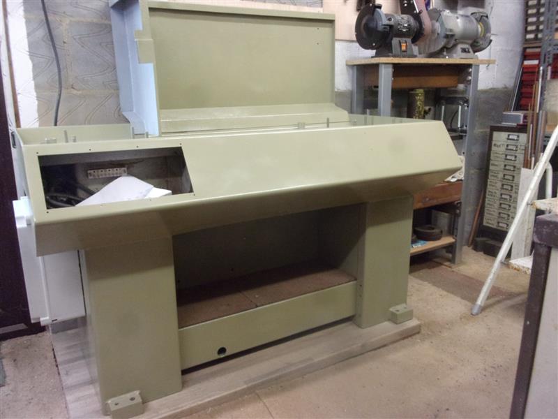
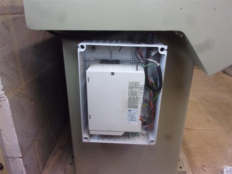
The lathe had a 3-phase motor fitted and an inverter was
discovered amongst the bits from the shed but no control panel for the front.
While I got an enclosure for the inverter fitted and wired up, a friend
designed and made an operator's panel to be fitted later. |
 |
 |
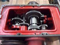
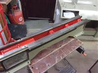
The bedway proved to be in good condition, the rust really
being no more than staining because of the induction-hardened ways. The
bedway was originally set on some sort of putty and this was carefuuly scraped
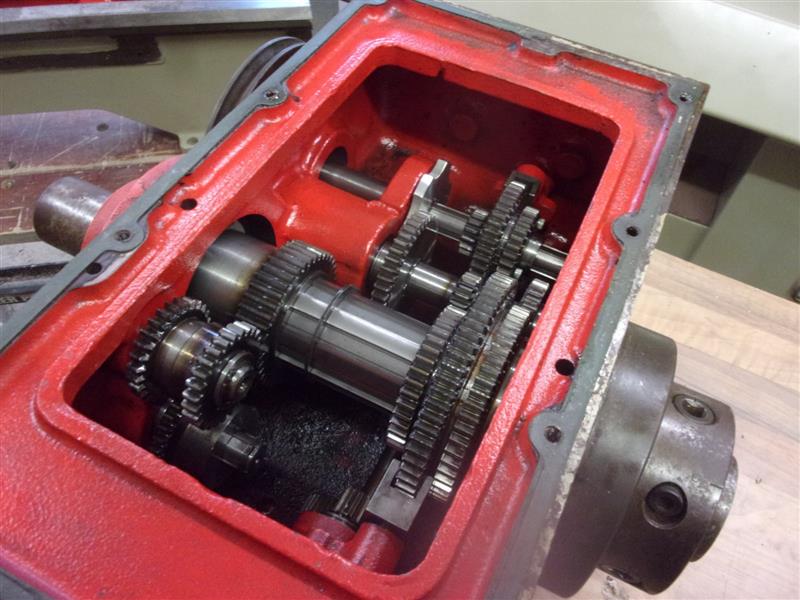
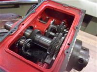
away from the bedway feet. The gearbox was drained and a close inspection
of the gears and shaft undertaken but all appeared to be in order. No attempt
was made to remove the main spindle because I had no way to accurately rebuild
it with the correct pre-loading on the bearings. |
 |
 |
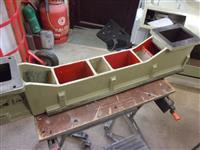
Getting the bedway back into position on the stand was
a time-consuming job. The feet on the stand were carefully adjusted to give
as level a surface as possible and silicone sealant applied around the eight
mounting studs. New packing pieces were placed where the old ones had been,
pressed in sealant, and more sealant placed around the mounting points.
the bedway was then carefully placed over the studs and lowered down onto
the packers. Finally, new nuts were run down the studs and the bed lightly
clamped to the base. This was left to settle for a couple of days before
doing anything else. |
 |
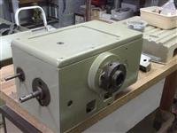 |
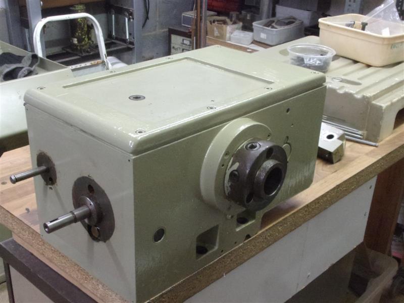
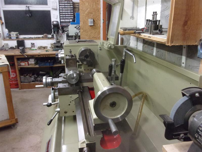
Re-assembly was pretty much a reverse of the strip-down.
New gaskets were purchased from Colchester Lathe Co and the gearbox refitted
to the bedway. Then the headstock was lifted back onto the bedway and bolted
down. The coolant tank was fitted with a replacement pump and the drive
motor refitted to it's mounting plate. |
 |
 |
The saddle was next followed by the apron gearbox and
then the feed drive shaft and leadscrew were wangled back into place and
the shearpins fitted. During reassembly, all the thrust bearings on the
ends of the shafts and the cross-slide leadscrew were replaced |
 |
 |
With all the mechanicals back in place, it was time to
finish wiring the lathe and my friend brought the user panel along so that
we could test it and set the inverter parameters. The panel also held the
switches for the light and coolant pump and these were wired up as well.
We had to make a couple of minor changes to the panel wiring because of
how the inverter was internally connected but after a little tweaking of
the settings, everything settled down well. |
 |
 |
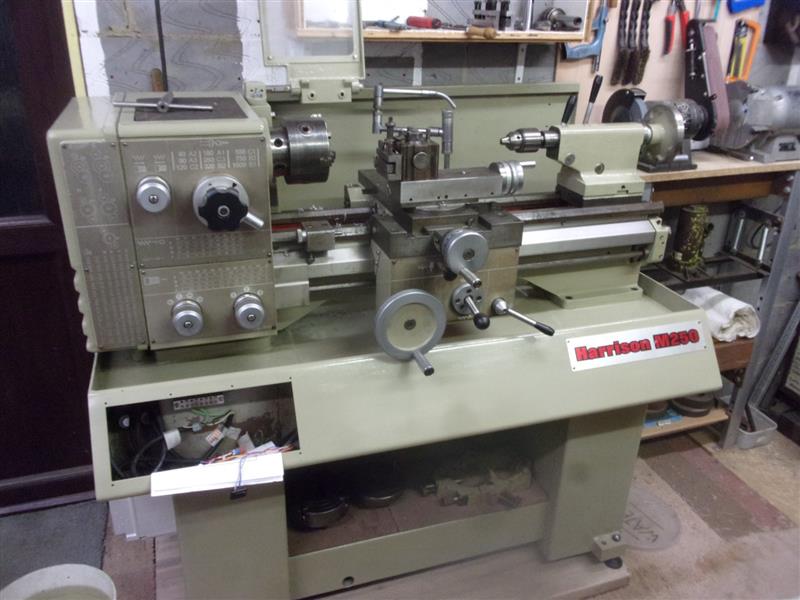
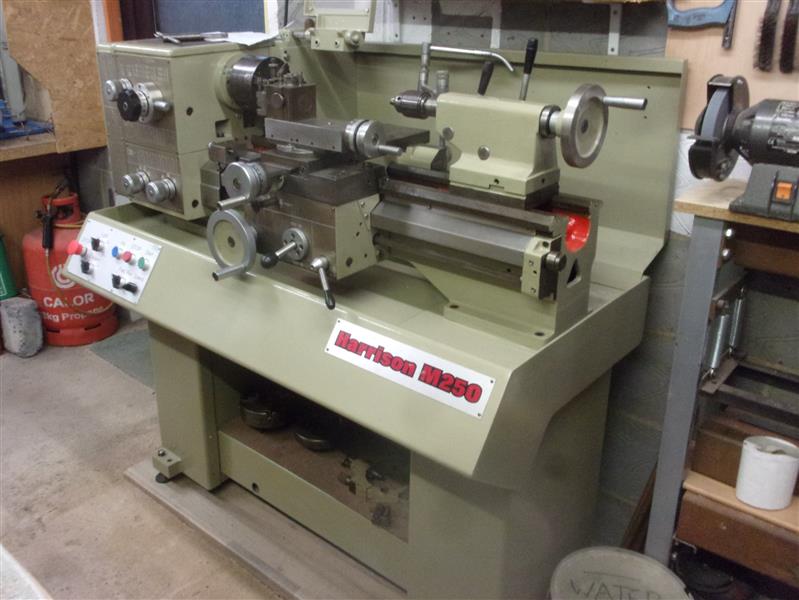
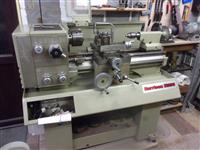
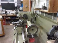
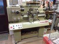
Following this exercise, I now have a first-class lathe
that is much more accurate than my other lathe and it's the first time I've
had flood coolant available since I shut my factory 25 years ago. It's a
joy to use. |
 |
| 2. Next Item |
|
|