| Drawing 1 - Mainframes |
| 1. The Frames |
|
|
| It seems that the first job we all do when starting a locomotive
is to cut out, or have made, the mainframes. The drawing called for 10
swg hot rolled mild steel (which normally has a black scale and is sometimes
called black bar or black sheet) but I made my mainframes from 3mm mild
steel guillotined from bright GCQ (general commercial quality although
I'm not sure if this classification is still used - about equal to EN3B)
sheet and marked out the basic shape in the time-honoured way using calipers,
the height gauge, dividers and scribers. I think the reason for using
hot rolled steel is that there is less chance of distortion after machining
the material but I have found no distortion in my mainframes. Because
I wanted to keep the outside distance of the frames correct, I made notes
on the drawings to increase the length of all the frame stretchers and
other bits by twenty thou. The frames were then cut and carved about in
a variety of ways including stitch drilling, cold chisel, hacksaw and
file. Once I had got to the finished shape and size, it was time to drill
a load of holes. At the time, I had a Bridgeport mill with DRO so the
obvious way was to do co-ordinate drilling after choosing a suitable datum
point. |
 |
 |
This was actually the front and top edges of the frame so the two
plates were clamped together and set up on the mill table with a lump
of MDF underneath to allow drilling right through. The Bridgeport table
is 42" long so I was able to do all the holes in one session. The only holes I didn't do at this stage were for the smokebox
saddle and the cylinder mounting plates. The drawing does not give positional
dimensions for the cylinder holes due to the inclination of the cylinders
and the need to get them accurately in line with the centre of the driving
wheels. These will be spotted through at the right time. I'm not happy
with the position and size of the holes for the smokebox saddle so I shall
put these in at a later date when I can see it all coming together.
I did make one mistake through my own carelessness - the hole on the right
should not be there! I will fill the unwanted hole with a bit of JB Weld
before final assembly |
| 2. Top Stretcher |
|
|
 |
The top stretcher is fabricated from a piece of 16 swg zinc-plated mild
steel, which I had guillotined slightly undersize, The other bits are the
two pieces of brass angle that affix to the frames and support the top plate.
The first job I did was to cut the 3/8 x 3/8" x 1/16" brass angles to length
and then mark out, drill and tap the eight 6BA holes in each. There's also
a cutaway in each to clear the bolt holes for the expansion link brackets.
These were then bolted to their respective frames and put to one side for
a while. There are eighteen equispaced 1/16" rivet holes on each side of
the top plate which were marked out and drilled, and I also marked out the
fancy cutaways using tracing paper. I then stitch-drilled them and chiselled
out the waste, finishing off the shapes with my dremel and a variety of
files. |
 |
 |
I clamped the mainframes together with the stays and spacer
between so that I could rest the top plate in position and clamp the plate
to the angles at each end. I also spotted through one hole each side, about
half-way along, with a 1/16" drill in my hand drill and dropped a pair of
1/16" rivets through to help keep everything in place. Then it was just
a case of unbolting the stretcher from the frames and drilling through the
rest of the holes, pinning with rivets as I finished each hole. On freehand
drilling the first hole about half way along, I promptly broke the 1/16"
drill. The reason for this was that, because of the flimsy nature of the
brass angle, the pressure of the cut was deflecting the angle down and away
from the drill point. At the moment of breakthrough, it promptly sprang
back putting a sudden sideways force on the drill. Result - a much shorter
drill. |
 |
To overcome the problem, I fixed a 5/16" packing piece to
the drill table to support the angle and from then on the rest of the drilling
continued without mishap. At the time I loctited the packing piece direct
to the table (ten seconds with a blowlamp breaks the bond when finished)
but I have since made various size packing pieces which bolt through the
table using a penny washer below. Finally, I riveted the bits together properly,
removed the clamps and drilled and riveted the final four holes. And here
I have the finished top stretcher ready to fit and bang on size. |
 |
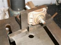
| 3. Bogie Stretcher |
|
|
 |
The drawing shows the bogie stretcher as a casting with a couple of bits of angle riveted to the sides but the
casting I got supplied with came as shown below. I started by fly-cutting the base to get it flat and then turned it over and
skimmed what would be the top of the angles down to size. Then I clamped it to an angle plate and cleaned up the fore and aft
faces. They don't do anything but it's handy to square these up to help subsequent operations. While the angle plate was set
up, I also machined the outer faces which fit between the frames, remembering that these are wider than the original drawing size.
Time to sort out the mounting holes. |
 |
 |
These were marked out on the surface table using the height gauge and digital vernier and
then clamped to another angle plate and the holes drilled. They were tapped freehand as I usually do. Next, I held the stretcher
in the vice and machined the inside faces, again just a clean-up, they don't do anything. I also cleaned up the face of the
pivot pin boss, again size doesn't matter, just cleaned up for a nut and washer. Finally, I marked out the centre of the pivot
pin hole and drilled and reamed it to size. I will make the king pin a snug fit when the time comes. |
 |
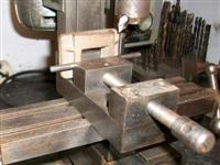
| 4. Front Beam |
|
|
 |
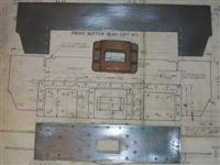
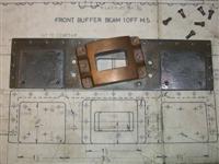
The front buffer beam assembly consists of the main beam, the drawhook strengthening plate, four pieces
of steel angle for connecting to the main frames and three pieces of 5/16" brass angle for affixing the footplate. The front
beam consists of numerous rivets which are decorative only. Unfortunately, I do not have a photo of the main beam before riveting
but I will describe how I made the various bits and fitted them together. The first job was to drill all the holes in the front
beam using the milling machine with the DRO. The mild steel blank, with a piece of 10mm MDF underneath, was clamped squarely to
the table and clocked up to set a datum. The clamps were positioned on the sacrificial areas at each end so that all the drilling
could be done as a single operation. I could have marked the plate out and free-hand drilled the holes but co-ordinate drilling
is more accurate and a wobbly line of rivets looks terrible. After sawing the four pieces of angle they were first milled to shape
and then flycut to make them truly square. The frame mounting holes were then drilled 2BA clearance and the angles bolted to the
frames, making sure they were square to the frame ends. One of my frame spacers was also clamped between the frames as close to
the angle as I could get it to correctly set the width. |
 |
 |
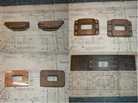
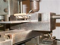
The front beam was then offered up and clamped to the outer angles and
the inner angles drilled through the beam, a rivet being inserted after
each hole was made. The clamps were then moved over to the inner angles
and the outer angles drilled and pinned as before. I am cheating a little
here because the front beam was already assembled so I ground out some of
the rivets and pulled it apart so that I could set up these two pictures
for the benefit of those who may not be quite sure what I was referring
to. Once all the holes were drilled, the beam was disassembled and everything
marked with felt tip to ensure the angle pieces didn't get mixed up. The
cutaways at the ends of the beam were sawn and filed to shape and any tapped
holes were threaded at this stage. The drawhook strengthening plate was
also made and this was the first thing to be riveted on, followed by filing
the rectangular hole to somewhere near size. Once the drawhook is made,
there will be another filing session to marry both parts together. All of
the dummy rivets were fixed next followed by the rivets to the angle pieces,
making sure the angles went back to their correct places. Once this was
finished, the buffer beam assembly proved to be a snug fit to the frames
so the packing piece was removed and the assembly bolted on properly. |
 |
| 5. Rear Beam |
|
|
 |
The rear beam comprises the large full-width plate from
18 swg mild steel and the main beam from 10 swg mild steel. The main beam
has two rubbing plates for the tender buffers riveted to it, and the central
stand-off bracket which the drawbar passes through is bolted to it with
6BA bolts. Both plates were first marked out and cut to shape by hand, except
for the platform support cutouts which will be done later, and were then
co-ordinate drilled using the DRO on the vertical mill. I could have marked
out and free-drilled the holes with confidence but it was easier on the
mill. |
 |
 |
The drawing suggests marking off eight of the holes from
the pressure brackets but I have chosen to do it the other way round, spotting
through the beam to the pressure bracket. The central stand-off bracket
is a fairly rough gunmetal casting and a little thought went into the machining
sequence. I decided to first mill the top and bottom edges square to the
sides but left twenty thou up on finished size and then face the back to
the nominal size. |
 |
 |
To get it level, I set four screws into the
rear beam and adjusted them to the same height. This then went into the
bottom of the milling vice and the casting settled on top. There is no size
given on the drawing but scaling from the drawing, which is normally inadvisable,
worked out at about 125 thou. It wont matter as long as I remember to make
the drawbar to suit, not just to drawing. I could have made this bit in
the 4-jaw chuck but it's a bit quicker in the mill. Then it was back onto
the angle plate to finish the edges all round, a load of filing and sanding,
followed by marking out and drilling the 6BA clearance holes. Be aware that
the hole positions are different on the tender pivot block - 1.1/8"
apart instead of 1". I had to modify my tender front beam because I
didn't check this detail. |
 |
It is essential that the holes for fixing to the pressure brackets are
drilled and tapped before riveting the rubbing plates on since they get
covered by these plates and tapping would be nigh on impossible after. The
photo shows the rubbing plates riveted on and the central stand-off bracket
about to be bolted on. Finally the two plates are fixed together with nineteen
10BA nuts and bolts |
 |
| 6. Pump Stretcher |
|
|
 |
The pump stretcher is just a bit of 10 swg mild steel plate and a couple of bits of 1/2" x 1/2" x 1/8" m.s
angle. The plate was marked out in the normal way and all the holes drilled, the only awkward ones being the two 1" holes.
The six pump mounting holes were done using the co-ordinates from the Zeus book. I had a 1" blacksmiths drill on a 1/2" shank
but didn't fancy drilling this size from scratch so I used a 24mm hole saw instead and used the 1" drill to open up to size.
This was done on a bit of 12mm MDF and I did make sure that the plate and MDF were well clamped down on the table. I wasn't too
worried about accuracy here since the top hole is just clearance for some pipework and the lower hole is for locating the pump
body - I can machine the O/D of that to suit. |
| My steel angle had a bit of a ropey finish
so I cleaned up one outer face on the belt linisher and marked out one of
the rivet holes on that face, making sure that, once assembled, the angle
would be about ten thou wider than the finished size. I also marked out,
drilled and tapped the three frame mounting holes on the other face of the
angle. After dropping a rivet into the one drilled hole and clamping similar
to how I did the top stretcher, the other three rivet holes were spotted
through and drilled with the rivet being dropped in each time. After messing
up some riveting once before by getting the holes slightly out of position
and having to open them up I always follow this procedure of drill, rivet,
drill, rivet etc. Once the whole caboodle was assembled, it was clamped
to an angle plate and the outer edges were skimmed on the mill to clean
the faces and end up with a snug fit between the frames. I may leave the
pump out altogether and rely on injectors and a hand pump. The pump stretcher
can stay, though, as it helps to stiffen the frames. |
 |
| 7. Horn Stays |
|
|
 |
The horn stays are made from gunmetal castings and just
need the horn mating faces and the frame stay lugs to be machined but I
chose to clean up the underside as well as it makes marking out and drilling
easier. Because the castings were reasonably flat, I was able to just give
the bottoms a quick dab on the linisher and then mount them on the mill
as shown. I clamped them onto a bit of packing but because there is only
room for one clamp, I set a fence at each end to stop the pressure of the
cut moving them. With this setup I was able to mill the back, sides, tops
and lug tops at one visit. It still needed a gentle touch, though. |
 |
 |
This just left the bottom to be machined which I was able
to do in the milling vice, and the 2BA clearance holes for bolting to the
horns which were marked out and drilled. I also dismantled the horns from
the frames and marked out, drilled and tapped the 2BA holes in these. I
have not drilled the frame stay holes in the lugs yet, if I get the hole
positions wrong it would distort the frames. These will be spotted through
from the frame stays which I will make next. The 1/4" hole for the spring
hanger can be sorted later, too. |
 |
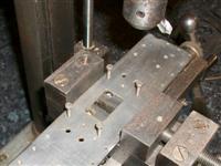
| 8. Frame Stretchers |
|
|
 |
The frame stretchers are the final part in holding the frames at the correct width and fit onto the horn stay
lugs. The drawing calls for six of these but actually only five are needed because the the leading stretcher on the rear horns
cannot be fitted, the bracket for the steam brake cylinder gets in the way. I have made them from 3/8" square mild steel, parting
them off to length on the lathe using the self-centering four-jaw chuck. However, they could just as easily be sawn oversize and
then faced or milled to length. There is nothing that needs to be particularly accurate here other than the holes. |
 |
| Next, I marked out the cross holes in each end and drilled them 3/32" before milling the two slots
using an endmill with the work held in my four-jaw chuck. I am going to be spotting through these to the lugs on the horn stays and
I prefer to use a small but reasonably rigid drill for this. I find it transfers more accurately and it's easy to open the holes to
size afterwards. Once the slots were in, they were offered up to the horn stays and spotted through. I also used my frame spacers
to ensure the frames were at the correct distance apart. At this point all the horn stays and stretchers were numbered so that they
could be dismantled, drilled to size and later reassembled without them all getting mixed up. It's probably unneccessary in this
instance but I think it's a good habit to get into and may save some grief at a later date. |
 |
 |
The last job was to turn the relief diameter in the centre
section. This was done by holding in the four-jaw chuck and supporting the
opposite end in a simple cup bored to be a snug fit to the square bar with
a centre in the back. Just sliding the parting tool back and forth along
the bar worked a treat despite the intermittent cut although I did take
quite a few passes. A bit of emery cloth to polish finished the job. The
last photo shows one section assembled |
 |
| 9. Brake Cylinder Bracket |
|
|
 |
The brake cylinder bracket is made from three pieces of 16 swg mild steel shaped and riveted together with a
couple of bushes to carry the pivot pin. When cutting out shapes that need to be bent, I like to draw the whole thing out as a
development first just so I can cut each part reasonably to size and to help decide when and where to drill any holes. Unfortunately
I only have photos of the finished article so I hope my description is up to scratch. I cut out the main part first and decided
to drill all the holes on the top of the bracket before bending but not the side holes in the tabs. These will be spotted through
from the frames. |
 |
| Once all the drilling was done, I then positioned the tabs by bending the two tabs on one side of the bracket in
the bench vice. To get the other side bent leaving the correct width, I made a former out of a bit of flat aluminium bar that I had
kicking around, milling it to about 3.260" wide. The gap between my frames is 3.395", and I subtracted two lots of 0.064" for the
thickness of the sheet steel plus a few thou for luck! I was then able to use the same former to put the right-angled bend between
top and back. Next I marked out and cut out the two side pieces, drilled the holes for the pivot bushes, a fraction undersized, and
then bent the tabs to a right-angle. Then it was a case of getting the sides fixed to the main part by spotting through and riveting
the bits together. To get the sides spaced correctly, I planed up a piece of timber since I didn't have any suitable metal and
clamped it between the side panels and then to the main bracket. It doesn't need to be particularly accurate as the other bits can
be tweaked to suit. After I had riveted the assembly together, I roughly marked out a couple of the side holes with a felt tip,
offered the assembly between the frames and located these holes to the corresponding holes in the frames. Then I clamped across the
frames to hold the brake cylinder bracket firm and spotted through all eight holes. |
 |
 |
The bracket was then removed from the frames, drilled and tapped 4BA and should have been ready for assembly.
However, I managed to strip one of the threads in the bracket - it's only 64 thou thick - so I have drilled this out to clearance
size and will use a nut and bolt instead.The drawing suggests that the two bushes are made of phosphor bronze but brass is perfectly
adequate here. The duty cycle on the bushes is practically zero and the boiler will expire before the bushes wear out. The pin and
bell crank will be made later when I make the brake cylinder and the bushes will be reamed to size at the same time. |
 |
| 10. Next Item... |
|
|
| |
|
|