| Drawing 9 - Link Motion
|
|
|
|
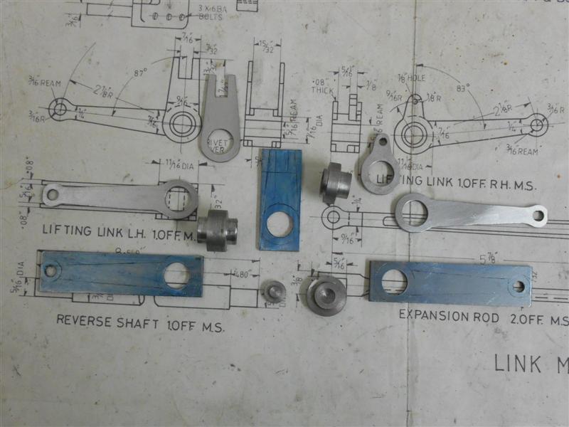
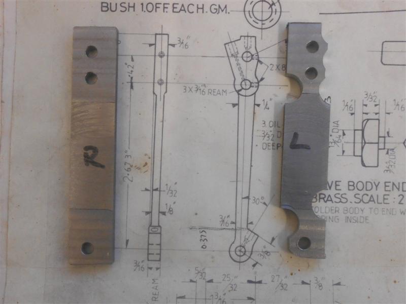
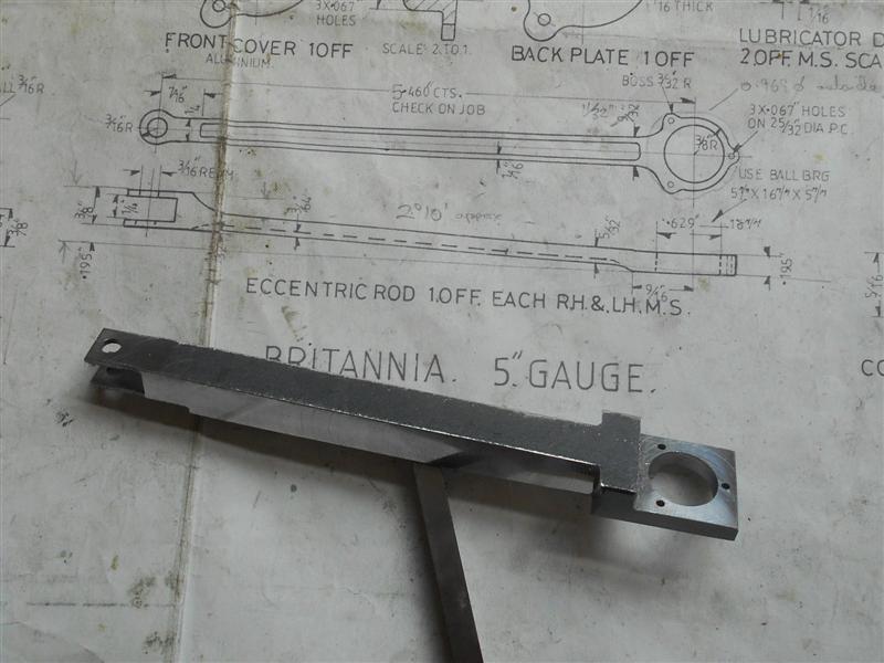
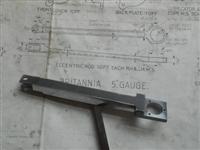
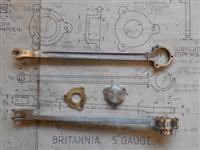
| 1. Left-Hand Expansion Link Bracket (see
the Assembly page for further work) |
|
 |
The left-hand expansion link bracket, like it's counterpart
on the other side, looks quite a complicated assembly at first glance. However,
once you get into started, it's not so daunting. I am using the available
gunmetal castings and they really are the pits with loads of material to
come off in some places, not much in others and one part of the profile
that can't be made as per drawing although it doesn't matter. They only
faintly resemble the full-size article and there are fabrications available
which are much more like the real thing. They also require a packing piece
to be made that fits between the bracket and the frames because there is
not enough material on the casting. It appears that the designer got his
sums wrong and no-one has ever bothered to have the pattern modified. I
shall be using offcuts of the frame material, 3mm mild steel, and need to
account for this in the measurements. |
| Before cutting any metal, the first thing
I did was to roughly measure from the as-cast back face to the centre of
the reversing screw bosses to get some idea of how much needed to come off
the back. I've set the height gauge for 2.065" and it looks like there's
about twenty thou to come off the back. I then checked from the centre of
the expansion link bearing to the top and bottom edges of the casting and
it appears that the bottom edge needs just a clean-up (with the nib removed,
of course) and can then become the starting datum. |
 |
 |
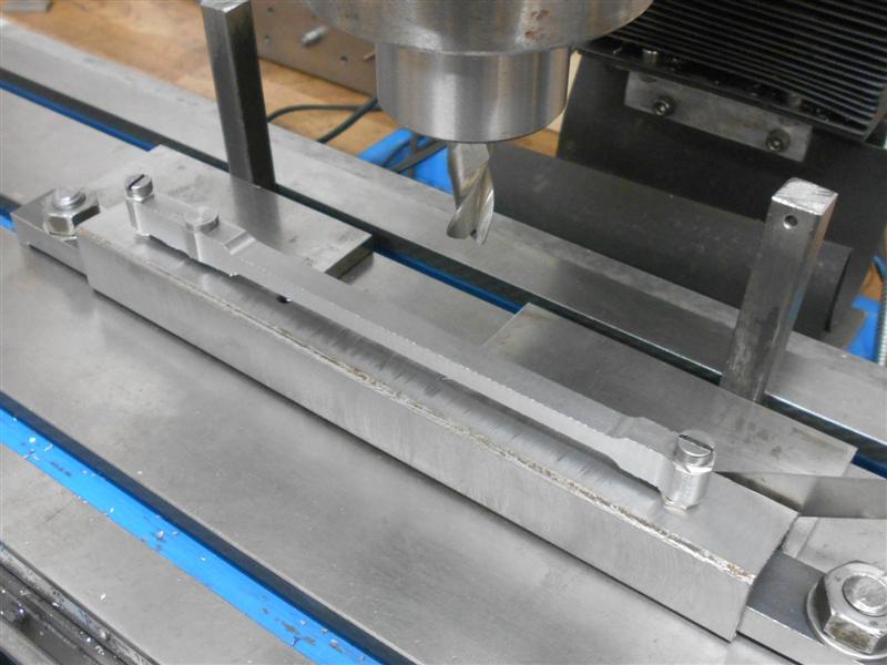
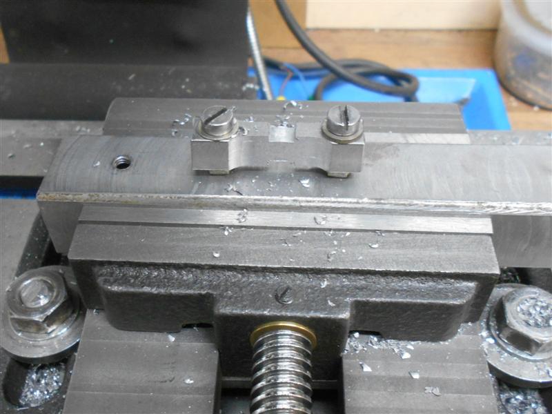
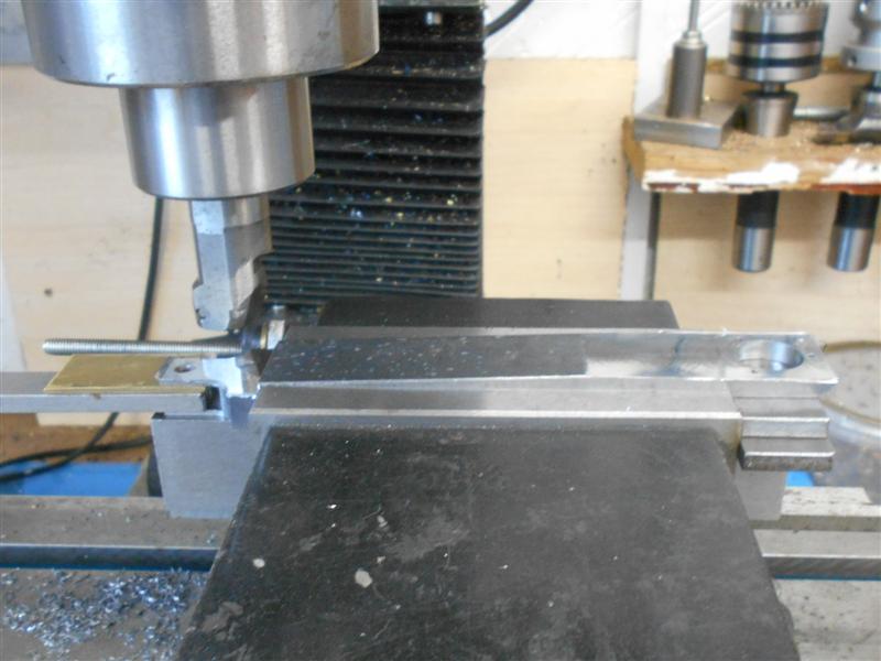
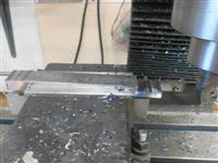
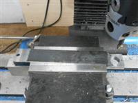
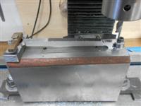
Holding the casting for the first machining took a bit
of thought but I found a way and then milled the back face flat, and also
cleaned up the angled edge at the same time. I expected it to sing like
a canary when milling the outer reaches but it was suprisingly quiet and
no evident chatter. Now that I had a flat back face, the bottom edge was
the next to be machined, followed by rotating round the fixture and milling
the other two edges. The picture on the right shows how I quickly align
the fixture using tee-slot packers and parallels when I don't need clocked-out
accuracy. The casting was positioned using a scribing block to set the centres
of the two reversing screw bosses at the same level for the first edge,
and then a square used against this edge for the next one. |
 |
 |
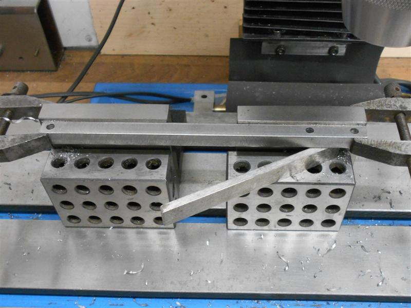
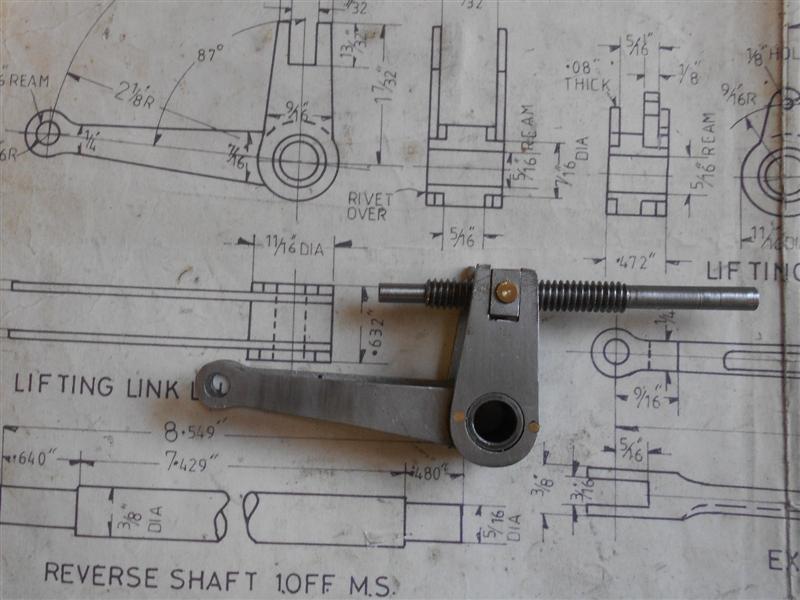
As each edge was machined, the flange thickness was also
reduced to 0.200" at the same. This is not a dimensioned item on the drawing
but they just about clean up at this size. It gives a flat seat for the
lower mounting bolts and make it easier for clamping. Whilst machining the
angled side, I also machined the area where the expansion link bearings
go; one is cast in situ and the other gets bolted on later. Although there
is a sacrificial piece at the outer edge, the pressure of the cut was bending
the casting slightly so I propped it up with a wedge. The pieces at the
bottom are a pair of wedges that I made as a ball-joint splitter about forty
years ago, nice to see that they still come in useful. The clamps on the
table are to stop the wedges drifting loose with the vibration of the cut. |
 |
 |
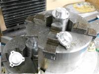
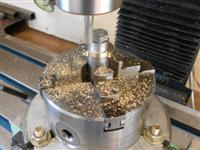
Next up was the insides of the reversing shaft bosses
where the left-hand side, or front of loco, gets machined away completely.
These were machined to the finished size of 1.5/8" and the outside of the
right-hand boss was also machined to 3/8". The top of the weighshaft panel
was cleaned up at the same time. I decided to do the centre section where
the weighshaft bush goes next and opted to do a full clean-up rather than
the spot-face shown on the drawing. This provides me with a mounting face
when I come to drill and tap the fixing bolt-holes on the back of the casting. |
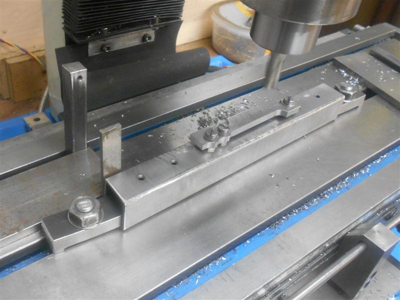
 |
 |
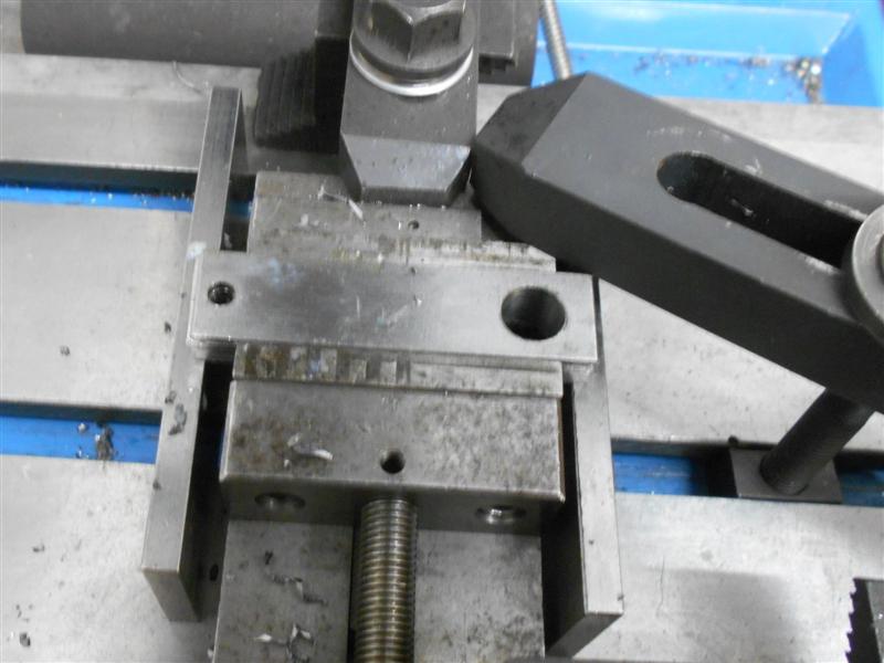
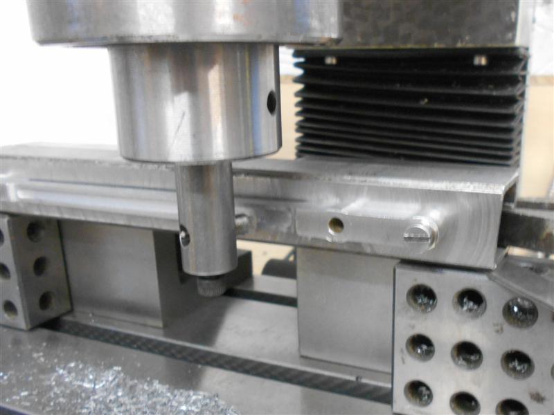
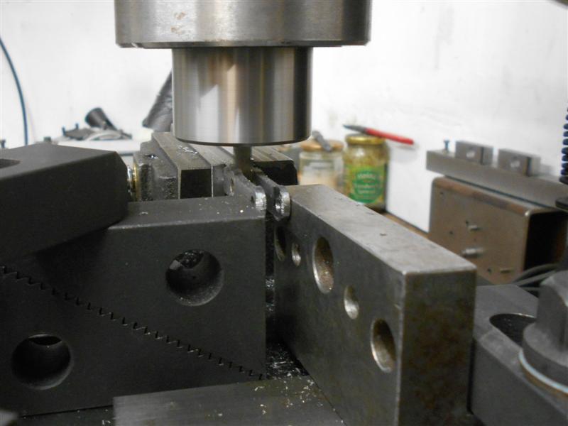
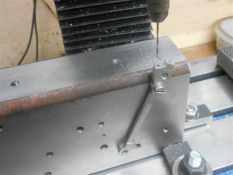
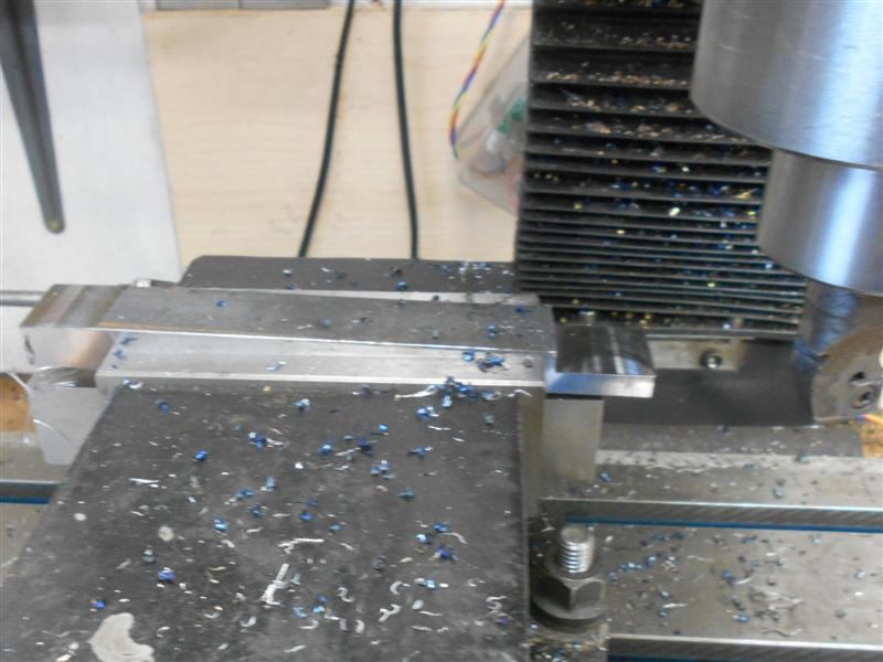
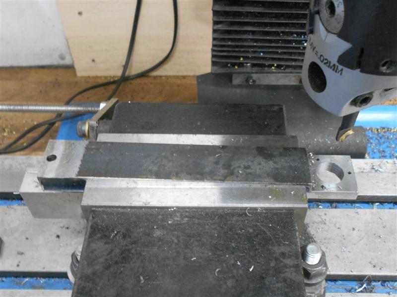
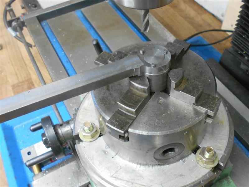
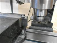
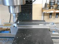
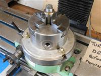
The rest of the faces were cleaned up in a similar fashion,
just re-clamping in various modes to suit and I shall skip over these operations.
These two pictures show the clamping arrangement for drilling the back.
The drawing says "Mark off from frame" but I've calculated where to put
the first hole - 5/16" up from the bottom and 1/4" in from the
right-hand side - and used the frame drawing dimensions for spacing. |
 |
 |
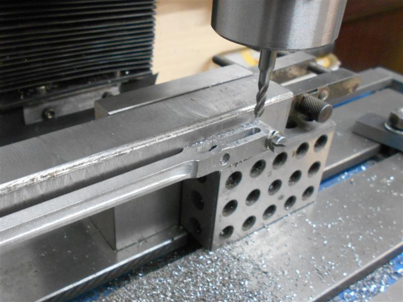
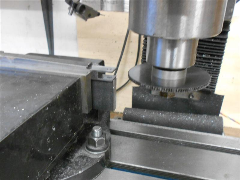
Once all the edges were cleaned up, I then clocked up
the fixture and set the valves centreline to zero. From here I was able
to drill the holes for the reversing shaft - a 3/16" pilot hole in this
instance - and the slot in the front plate, doing the top half after the
holes and then tilting the casting and doing the lower section. The corners
of the slot will be filed square in the final dressing. The outside bearing
carrier has to be machined at some point and was now separated from it's
right-hand counterpart. They are a slightly different shape and won't fit
properly if mixed up. |
 |
 |
After machining all over to get flat surfaces the mounting
bolt holes are drilled and tapped 6BA. The drawing doesn't give any dimensions
and I have made mine at +0.475", 0, -0.475" from centre of casting, and
marked the drawing accordingly - in a few years time, if I need to revisit
this item, I won't remember the hole positions. Matching clearance holes
were drilled in the expansion bracket and the picture shows the sacrificial
waste to the side. |
 |
 |
The two parts were then bolted together and the waste
removed flush with the bearing carrier followed by the angled edge being
milled to shape. The fixture was then set up one more time to drill the
remaining holes, starting with the hole for the weighshaft bearing drilled
and reamed 1/2" diameter followed by the expansion link bearing carriers. |
 |
 |
It appears that the positional relationship of these
two holes is important and this is where the DRO really pays off. Because
of the flimsiness of these, packers and wedges were used to support them.
After drilling and reaming the main hole, the four flange holes were put
in the top carrier, then the carrier removed and the lower one drilled.
I will now spend some time prettying these up with the Dremel and then make
the various bushes and bearings. Also, the front reversing shaft hole was
reamed to 9/32" diameter and the rear one tapped 5/16"" x 40 ME |
 |
 |
I have made the expansion link bushes from phosphor bronze
because they are going to get a fair bit of wear and the four bolt holes
were drilled on the mill using co-ordinate drilling. There are two for each
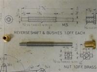
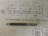
side and they are the same both sides. I've also made the reversing shaft
bushes and the weighshaft bushes but these have been made from brass as
they won't get anything like as much wear. The backing plate has also been
made from some 10swg mild steel and all the parts assembled together although
I still have to make the reversing screw which is a left-hand square thread
and will need some thought. The assembly has been temporarily bolted to
the mainframes and work will now start on the right-hand bracket. |
 |
| 2. Right-Hand Expansion Link Bracket |
|
 |
The right-hand expansion link bracket is very similar
to the left-hand bracket, although a mirror image, so there is no point
covering the same machining operations all over again. This is the starting
point and, like before, the castings are very rough and also require the
packing piece behind them when assembled. The one thing that is a little
different is that the amount of material available between the rear mounting
face and the inside of the expansion link bearing face is a bit mean. I
am going for a full clean-up but may need to increase the packing piece
thickness to compensate to get the link and valve centre-lines the same. |
 |
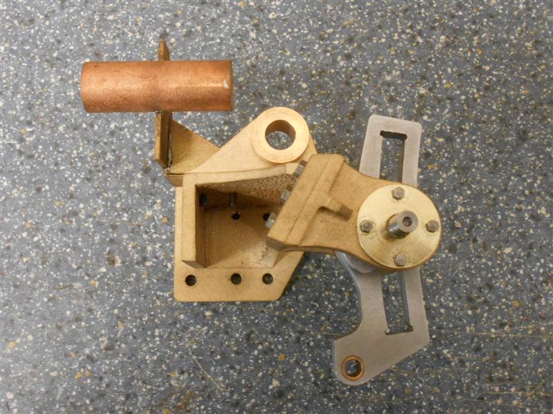
 |
This bracket also carries the restoring spring mechanism
and this has been fabricated out of some brass sheet, a brass bung and a
length of 15mm copper tube. The bung and tube have chamfers to create a
fillet and were a tight fit together, with the three parts then being soldered
together. |
 |
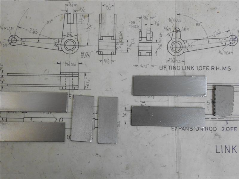
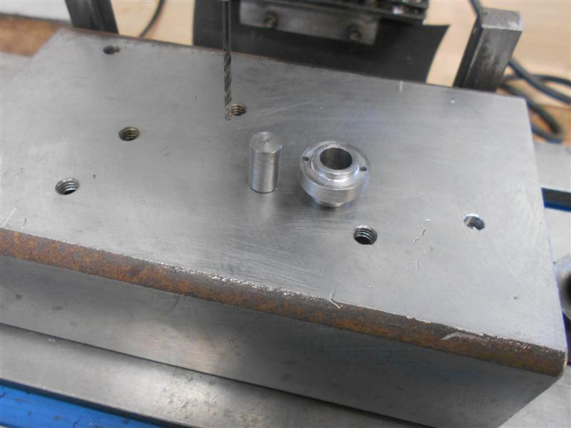
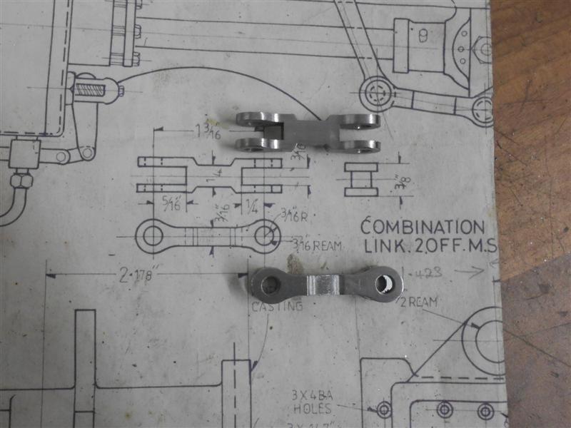
| 3. Expansion Links |
|
|
 |
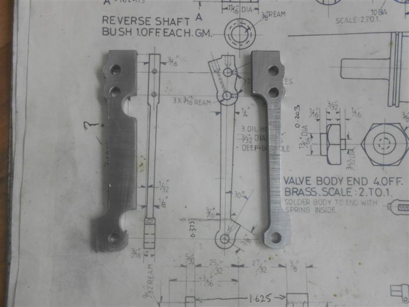
The starting point was to cut a pair of blanks from some
black flat bar. On these drawings, all the expansion link parts are drawn
at twice full scale so I can't trace the outline and tranfer to the material.
These have been machined all over to give a flat plate of the final thickness
(1/4") and, using the centre of the trunnion pin as the x0,y0 datum, a locating
point drilled and reamed 3/16". This was followed by working out the absolute
positions of the three 6BA clearance holes for bolting on the trunnion brackets
using the pitch circle co-ordinates in the Zeus book and, finally, the hole
for the eccentric rod. Although this should be 1/4" diameter reamed, I've
left it at 3/16" dia for the moment because I have a filing button of this
size for the outer form. |
 |
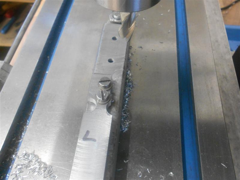
 |
I had a couple of pieces of 2" x 1/2" flat
bar going spare and used these to create the machining fixture for the next
few operations. At the lefthand end I have made a 5/16" diameter pivot point
which gets bolted to the table and the DRO centred on the pivot. At the
right-hand end another piece acts as a pressure pad with a fence spaced
a few thou over the half-inch bolted on top which holds the working plate
captive but free to slide back and forth. The working plate is a ten inch
length of the same material with two holes drilled and reamed 5/16" at the
left-hand end. The first is for the outside radius of the link and the second
is for the radius of the slot in the link. At the other end are three holes
drilled and tapped 6BA and a hole drilled and reamed 3/16" to take the locating
pin. I have also drilled and tapped a couple of M6 holes to take a pair
of clamps. Finally, I have made up a crude leadscrew arrangement from some
M8 studding and a couple of bits of brass to allow controlled movement of
the working plate. |
| The leadscrew works because the two brass
bits are free to pivot in the respective plates and there is a small bit
of plastic under the grubscrew in the leadscrew nut that reduces the backlash
of the thread to a minimum. It all looks a bit Heath-Robinson but it does
work and the next photo shows completion the first operation. I roughed
out using plunge cuts and finished by taking two radial (side-cutting) passes
at ten thou and a final one at five thou to finish at the correct dimension.
The fixture was then adjusted and set up using the second pivot point and
everything re-centred. |
 |
 |
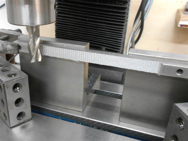
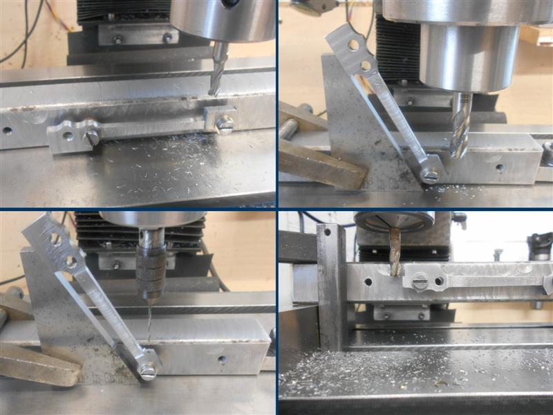
I then marked out the top and bottom extremities of the
link by clamping the workplate and moving the table to plus and minus 1.218"
on the DRO and scribing a very short line by dragging the chuck with a centrepoint
loaded in followed by resetting the table to zero and pivoting the workplate
till the mark matched the centrepoint at the edge. The workplate was then
clamped, a 1/4" dia cutter loaded, the table move out and the angle formed
with multiple passes until I reached 0.125" on the DRO (half the cutter
diameter). A similar procedure was used to mark out the extremities of the
dieblock guide and four 1/16" diameter relief holes drilled before milling
the slot. Using the pivot block and adjusting to centre each time ensures
that all the holes and slots are in the right place but trying to mark this
shape out from dimensions only would be a nightmare. |
 |
 |
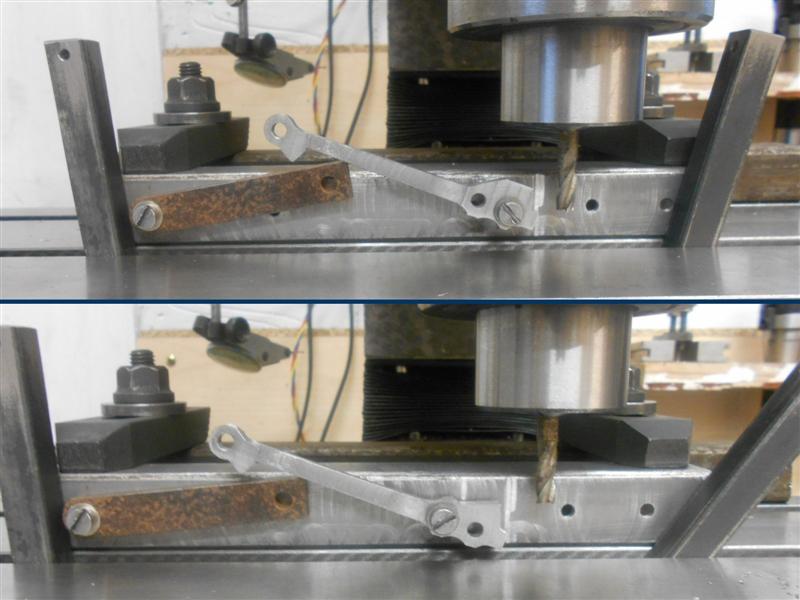
The final operation with this setup was to mill out the
slot and for this I first punched the locating pin in the workplate down
below the surface and then roughed out with a 3/16" dia slot drill using
plunge cutting, removing the leadscrew arrangement and just moving and clamping
the workplate by hand. Then I changed back to a 1/4" dia cutter and repeated
the plunge cuts. Finally, I dropped the leadscrew back in and ran the cutter
back and forth in the slot to clean the sides. |
 |
 |
Now that the slot was finished, it was just a case of
getting the exterior shape reasonably correct. The working plate still came
in useful as for milling the lower angle because it just needed to be set
to the thirty degree angle and the lower section milled away. The rest of
the outside shape was marked out using one of the unfinished trunnions to
scribe the rear circular shape and digital vernier to mark out any other
dimensions. They don't show up particularly well but this photo gives the
general idea. Look closely and you will see some lines. |
 |
 |
From this point on, it was mainly hand-work sawing off
the excess material before filing, grinding and linishing to get the final
shape. And here are the two links: they just need the eccentric rod bearing
hole opened out and a PB bush installed plus a little more polishing. I'm
quite pleased with how these have turned out, and it just goes to show that
complex shapes can be made with the simplest of equipment if one just takes
the time to work out how. I will probably avoid laser-cutting for a while
longer, it's far more satisfying to make it ones-self. |
 |
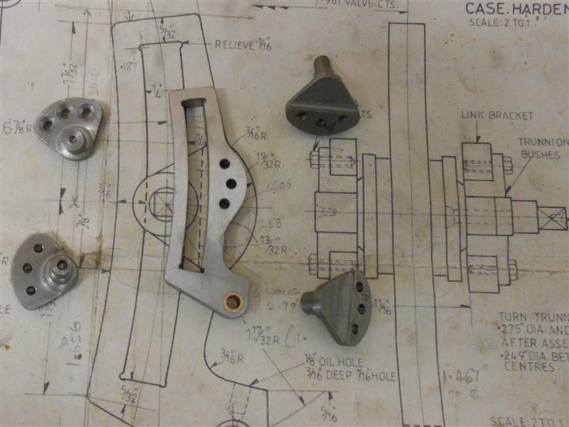
| 4. Expansion Link Trunnions |
|
 |
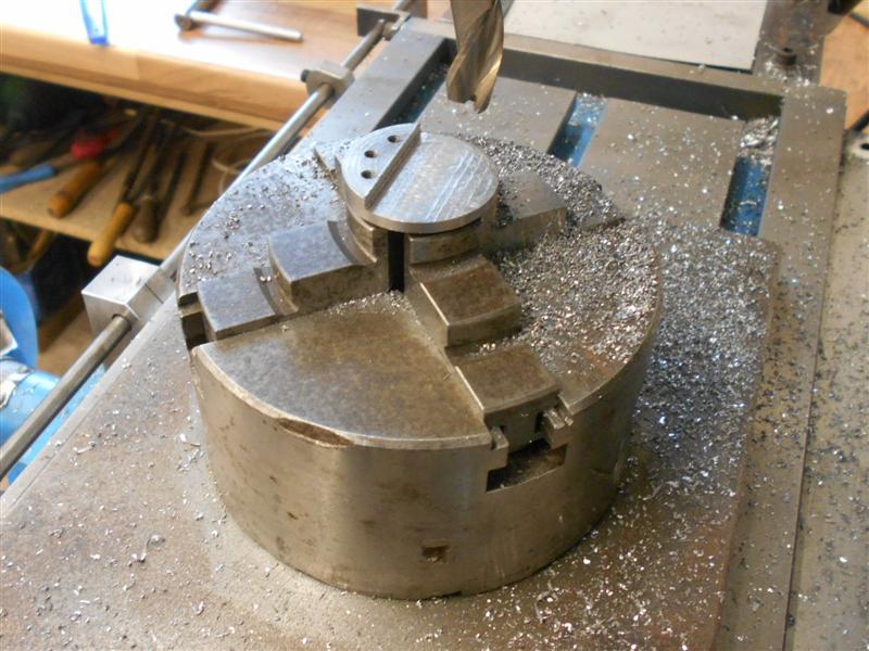
The expansion link trunnions have been made from 1.1/4"
dia mild steel as complete articles although the drawing seems to indicate
differently. All four billets were turned to 1.3/16" diameter and faced
off (two of each size) and then held in soft jaws for the second and subsequent
operations. This was just straightforward turning and doesn't require description.
Then they were drilled on the mill using the same technique as for the expansion
links and then the backs milled to create the clearance for the radius rod. |
 |
 |
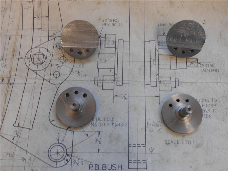
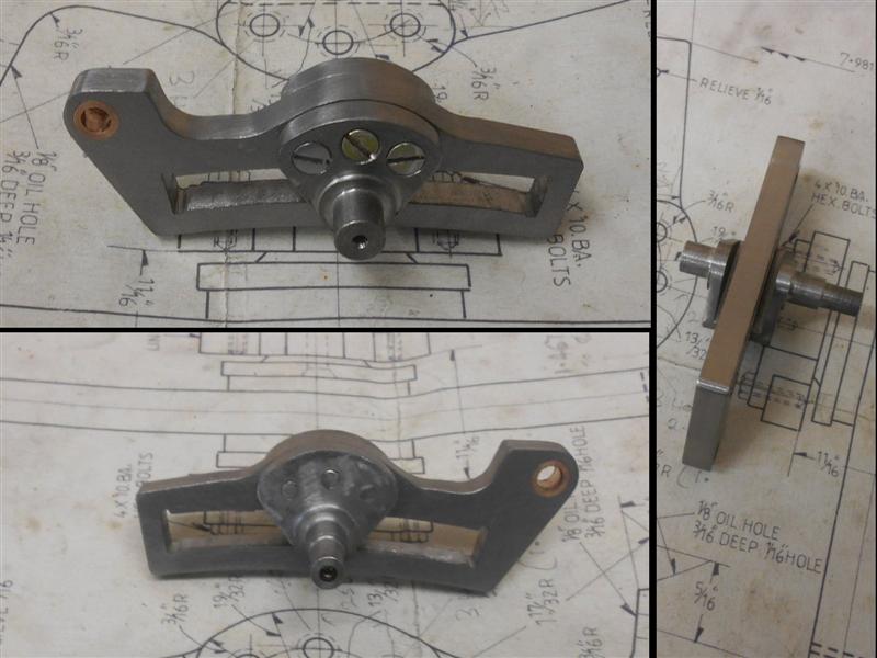
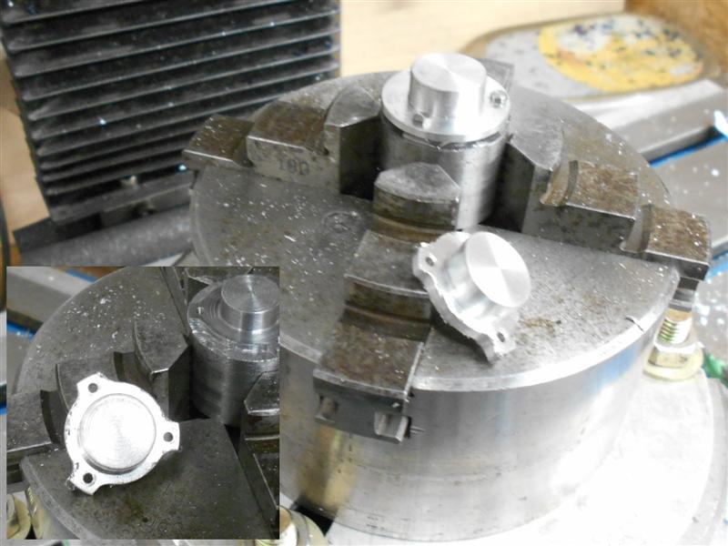
The inner pair, with the short axle, were drilled 6BA
clear with deep countersinks and the outer pair were drilled and tapped
6BA. Because of an issue with sloppiness, these were later remachined to
cater for 1/8" BSW. To the right is a composite photo showing three views
of the nearly-completed link assembly. The hole for the eccentric rod has
been opened up and the phoshor bronze bush has now been inserted in the
link. |
 |
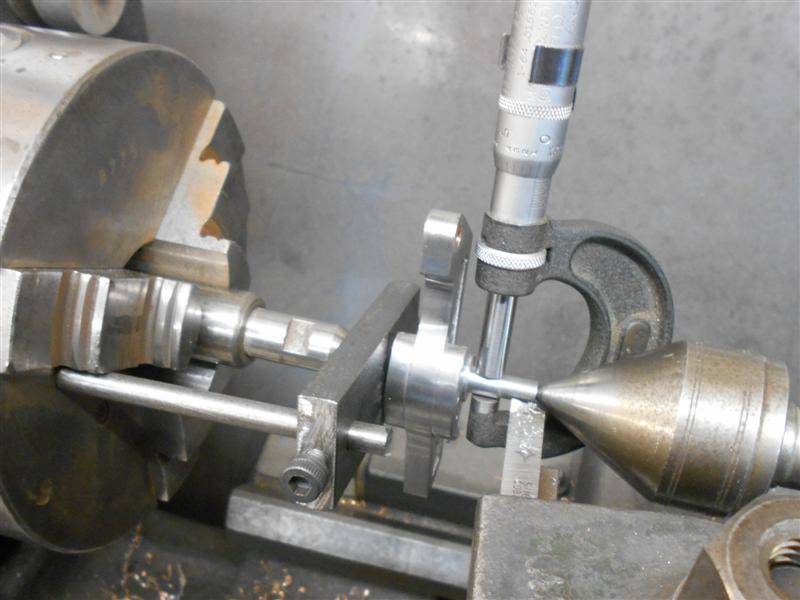
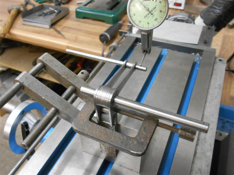
 |
The various small jobs on the expansion links have now
been done, the expansion link brackets have been line-reamed and the expansion
link assembly put up between centres and the journal turned to exactly 0.250".
The brackets were disassembled and then reassembled with the expansion link
assembly in place. They rock too and fro but are a little stiff at the moment
and will ease when in use. The right-hand bracket is shown here. |
 |
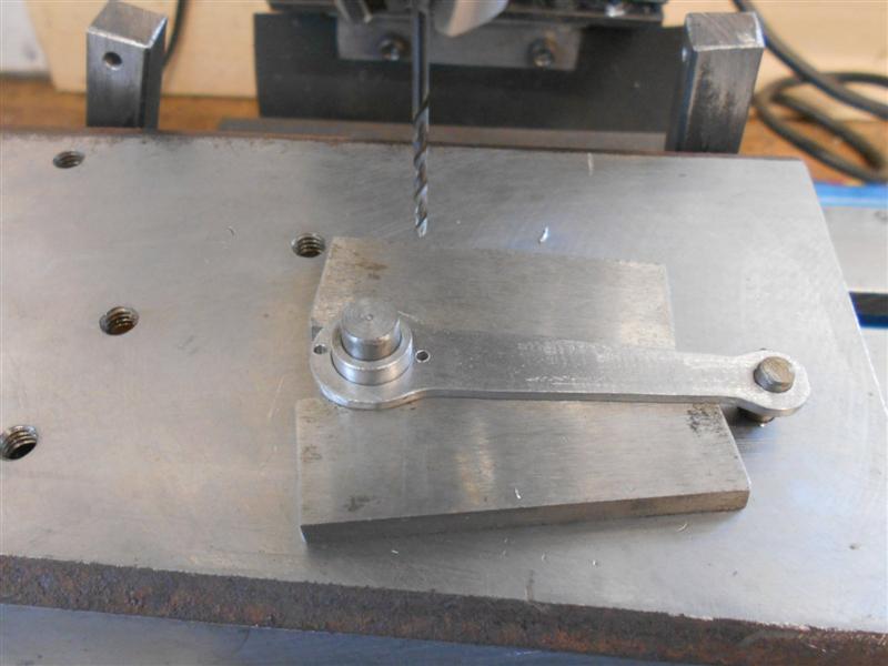
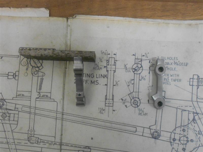
| 5. Lifting Link Bellcranks |
|
|
 |
The drawing shows the lifting links being fabricated from
some pieces of 14 swg mild steel mounted on a central boss and "riveted
over" but I can't see how this can be very accurate, or rigid for that matter.
I decided to try soldering the parts together and started by cutting out
the arms from some offcuts of 2mm M.S. sheet as there is only a couple of
thou difference in size. The longer arms are the same size on both sides
of the loco so the four pieces were machined as a single item, first milling
the sides to clean up at 11/16" followed by drilling and reaming the 7/16"
hole at one end and the 3/16" hole at the other. Because of how I held them
in the vice, I added a top clamp (moved aside for the photo) to ensure that
they remained held together but drilling this way gives more support to
the point of the drill and ensures a reasonably round hole. |
 |
 |
On the lathe, I made a pair of filing buttons and the
two central bosses, noting that they are different sizes. The arms were
then marked out and the basic shapes formed using files and sanding drums.
When it came to soldering time, I played with various ways on holding the
assemblies together whilst soldering and this gave me the most trouble.
The arms to the reversing screw are at 87 degrees to the lifting arms and
the arm to the return spring on the other side is at 83 degrees. I made
various spacers to fit between the arms and hold them square, set them up
on the mill and fixed the angle using clocks but one problem kept getting
in the way. |
 |
 |
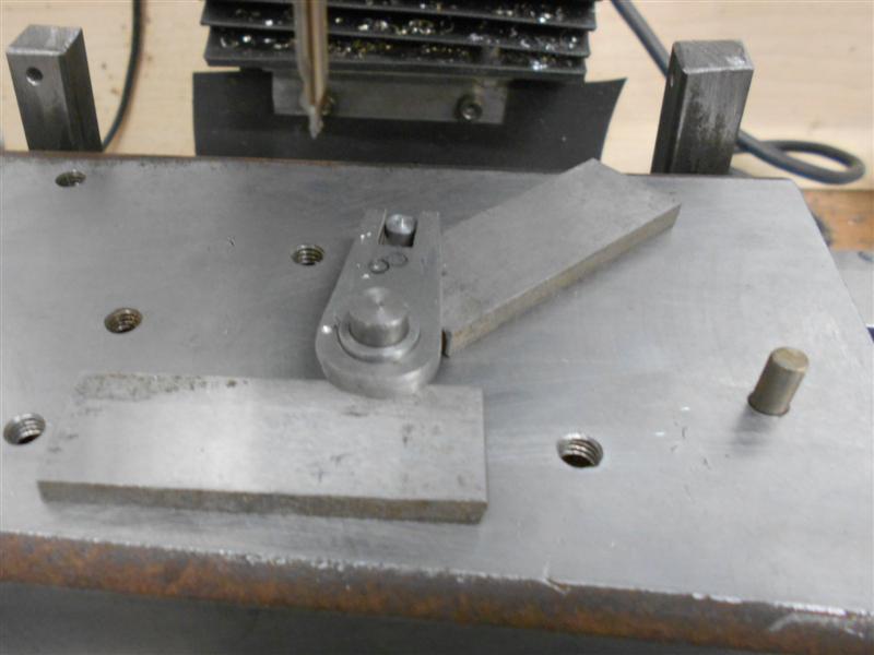
To keep position, the assemblies had to be kept tight
and to get solder in anywhere they had to be loose. After many frustrating
hours trying to make this work, including scrapping one boss and remaking,
I decided to abandon the idea of soldering and use pins instead. To get
this under way, I started by making a simple fixture on the mill to load
the centre bosses to and drilled two 1/16" dia holes through. The pin was
then sleeved up to 7/16" to suit the long arms and a further locating pin
added to the fixture. The arms were then drilled with a pair of 1/16" holes
in the boss end at right-angles to the arms. |
 |
 |
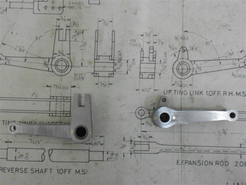
The fixture was then modified again to accomodate the
other three arms. To set these at their respective angles, I worked out
the hole positions for the locating pins using sine tables and set the position
on the DRO. The holes were then drilled at the same position as all the
others. Finally, the holes in the outer arms were countersunk and the various
parts were riveted together with some home-made rivets cut from 1/16" dia
brass bar. These will now be put aside until assembly time when a cross-hole
will be drilled at forty five degrees through each of the bosses and the
weighshaft, and pinned with taper pins to keep them in position. |
 |
| 6. Radius Rods |
|
|
 |
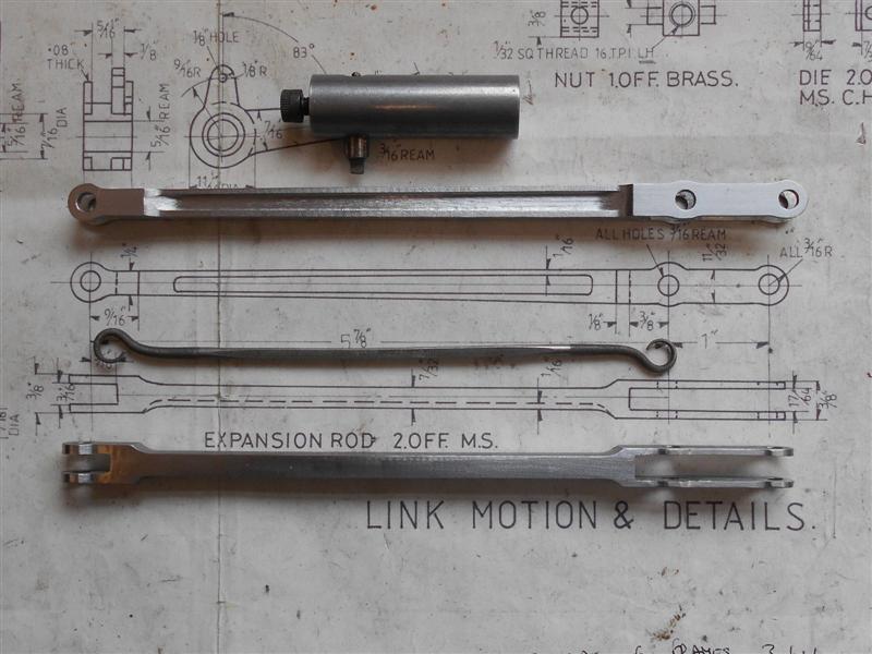
The radius rods, or expansion rods as they are called
on my drawing, were made from some 10mm square black bar which was cleaned
up all over to finish at 3/8" square. I then mounted them to my pair of
angle plates and drilled and reamed the three 3/16" holes using the DRO
for precise positioning. Using the same style of setup, I then necked the
rods using a 12mm end mill. I prefer to rough out using a plunge-cut, which
can be seen from the finish at this point, followed by a sliding pass to
clear the high spots and a second pass at finished depth, about an extra
six thou in my case. There is less stress on the machine and, as a bonus,
I have loads of 12mm endmills and use them where I can. |
 |
 |
My next job was to make a fixture to bolt
the rods to and this was made from some 1" thick-wall box section, milling
square then drilling and tapping the fixing holes. I used 2BA as it's a
good fit in the 3/16" reamed holes and the DRO ensured that the holes were
in exactly the right place. The end sections between the two holes were
done first because this part is parallel to the centreline of the rod and
the fixture was then repositioned to machine the tapered sides of the rod.
I worked out that I needed to offset one end by about forty thou to achieve
this, and feelers were used to act as packing between the fixture and the
table slot wedges. After machining the front, the feelers were moved to
the opposite end so that I could mill the other side. |
 |
The flycutting bit that I had made for the connecting
rods was too large for these radius rods and I made a new tool bit from
an old centre-drill. I had planned to turn the fixture ninety degrees and
then mill out the flutes but I forgot to allow for the bolt holding the
tool bit in place so plan B was adopted which entailed lifting the fixture
up somewhat. The angle plates were brought back into use and the feelers
placed under one end to set the correct angle for the first pass, then moved
to the other end for the second pass. I described the basic setup back at
the con rods page and won't repeat that here. While I had the angle plates
set, I also took the opportunity to rough out the slots and set the finished
depth of the slot. The long end,in particular, gets a bit flimsy further
down the job. |
 |
 |
To complete the opening out of the slots to the finish
size, I held them in the vice and surrounded the sides with a pair of fences
to give extra support and then gently milled them out with a 3-flute slot
drill, working outwards from the cross-holes all the time. Because the side
walls are so thin, coming in from the front end courts disaster as the endmill
will probably pick up the side and bend it inwards. Not worth risking after
this amount of work. And then, to finish, a bit of time spent deburring
and polishing up. Getting into the flutes is not easy because of their small
size but I was able to clean them up a bit more with the file shown in the
last photo. The tool I used to create the flutes is shown also. |
 |
| 7. Union Link |
|
|
 |
When I made the radius arm machining fixture, I drilled
and tapped the two 2BA holes for the combination link at the same time.
The pair of holes in the combination link were drilled and reamed 3/16"
in a vice and then bolted to the fixture so that the rods could be necked,
as before. A pair of 3/8" dia washers under the clamp-down screw heads acted
as visual limit markers to ensure that I didn't get too close to the ends
with the endmill. This time there is no fluting of the rods, just a central
relief with angled edges and this was done with an endmill that I had in
the "specials" drawer, although it could just as easily been filed to shape.
They were then loaded back into the vice and the slots milled with a 3/16"
dia cutter, no special support being required this time as they were much
more rigid. A quick clean-up all round and these now get stored until assembly
time. |
 |
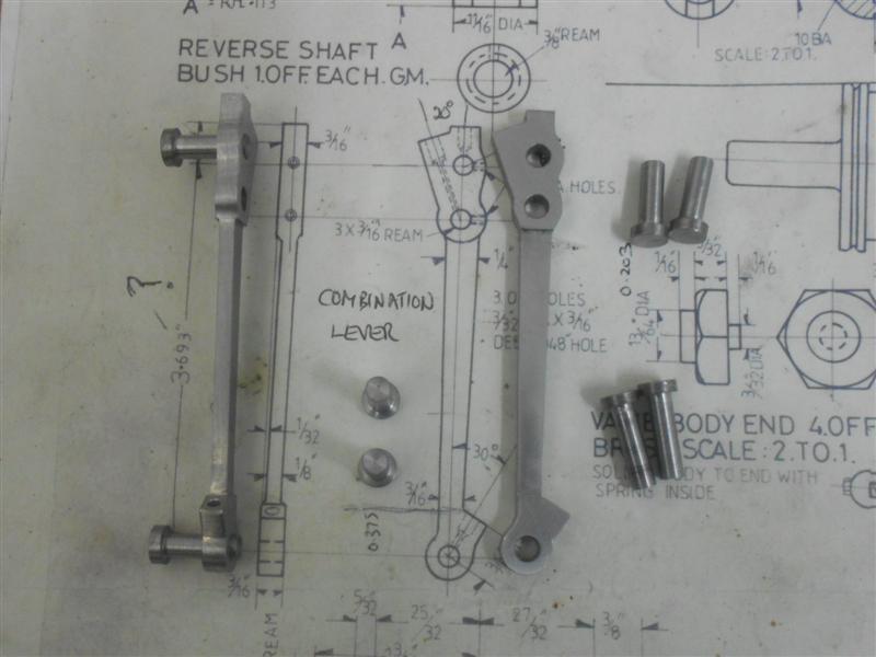
| 8. Combination Lever |
|
|
 |
The combination levers were once again made from black
bar milled all round to clean up. There is no fluting on the items but the
centre section is thinned from 3/16" to 1/8" as well as being tapered from
1/4" down to 3/16". The drilled and reamed holes on these are precisely
dimensioned on the drawing and it was obviously important that they were
accurately positioned, otherwise they would have been dimensioned in fractions.
After drilling and reaming the holes in the milled blanks, the drill jig
had three extra holes put in it at the same positions and clamped square
to the table. The hole for the radius arm pin was set as the zero datum
and a variety of roughing out operations were then undertaken by calculating
the various finishing positions for the cutter. Once again, the washers
acted as visual limit markers in the uncalculated axis and the next picture
shows one of the combination levers after the first round of cuts. |
 |
 |
The fixture was then moved over at one end and the taper
formed on the central section. Flipping the workpiece over allowed for maching
the opposite side without having to adjust the fixture a second time. It
can be seen that the basic shape is starting to develop here in the picture
on the right. |
 |
 |
The waist of the combination levers were thinned by 1/32"
each side next and then the fixture was turned ninety degrees and a variety
of other operations performed by mounting the levers on the side of the
fixture. |
 |
 |
One of the other general-purpose fixtures that I made
a while back came in useful because of it's height, a matter of moments
to drill and tap a 2BA hole high up allowing me to drill the oiling holes
in the end of the levers. As always, the final work was to clean things
up with files and rotary sanding drums and the final picture shows them
nearly finished, along with a bunch of pivot pins that I made on the lathe
whenever the mill was able to run using the power feed. Since taking that
photo, I have also drilled and tapped the 8BA holes shown on the drawing.
I was debating leaving them out until I realised that the die block on the
valve guide uses headless pins that need to be held captive and this addresses
that issue. |
 |
| 9. LiftingLink |
|
|
 |
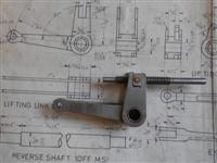
The lifting link connects the lifting link bellcrank to
the radius rod and is very similar to the combination lever but with one
less hole and were made in the same manner. I'm only including these with
a couple of pictures for completeness. The only variation to my usual way
of making these was to form the raised pivot bosses by bolting the workpiece
to a mandrel in the lathe. Based on the drawings, this is the only one of
these parts that can be turned this way. |
 |
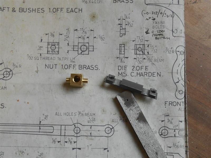
| 10. Reverser Screw |
|
|
 |
I have been finishing off a few items related to the motion,
notably the reversing screw that operates the lifting link bellcrank. The
two bushes are simple turnings from brass bar and the screw was made from
some 1/4" dia silver steel, cutting a 1/16" pitch acme-style thread. I now
needed to produce a matching nut and after spending quite some time grinding
a very fine internal screwcutting tool, I promptly broke it after a couple
of cuts. My lathe is a bit too cumbersome for such delicate work. Instead,
plan B was implemeted, which was to cut another leadscrew and make it into
a tap. This went well until I came to tap what I thought was brass but turned
out to be phosphor bronze. Broken tap!! Plan C was to hurl the whole lot
at the workshop wall and buy a 1/4" x 20 Whitworth left-hand tap and button
die. Remaking the reversing screw and the nut, now in bronze, was relatively
easy. |
 |
 |
I also made the tiny dies that sit in the bellcrank, finding
it easier to make them as a pair by milling down a length of ground flat
stock and separating them with a junior hacksaw at the end. It was also
much easier to maintain accuracy like this. Unfortunately, the picture I
took of the setup became corrupted but here the left one shows them unseparated.
The parts have been assembled leaving just the cross-drilling and reaming
of the taper-pin hole that will fix the universal joint to the end of the
shaft. Whether or not this is a good idea only time will tell. At the moment
there is absolutely no backlash in the nut and screw but it may be too stiff
to turn in normal operation. I'm not worried about how it looks, however,
it's buried under the running plate and can't be seen. |
 |
| 11. Eccentric Rod |
|
|
 |
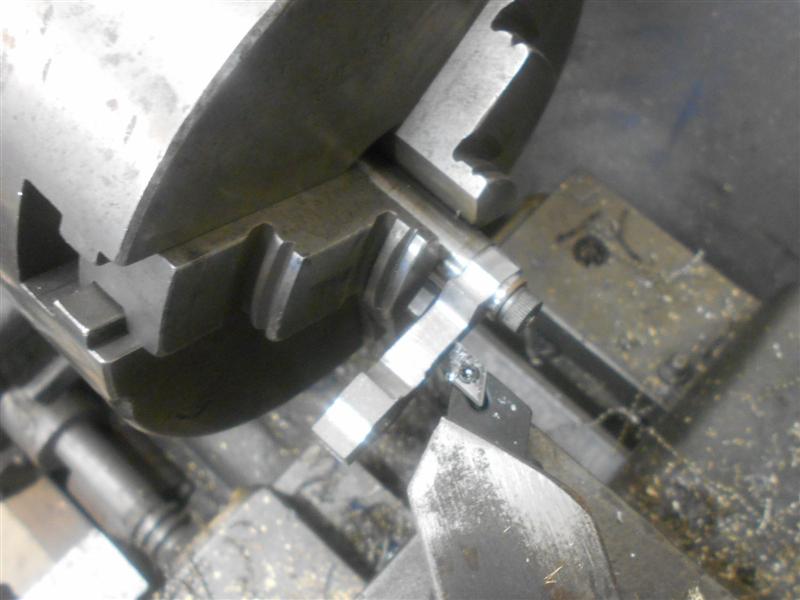
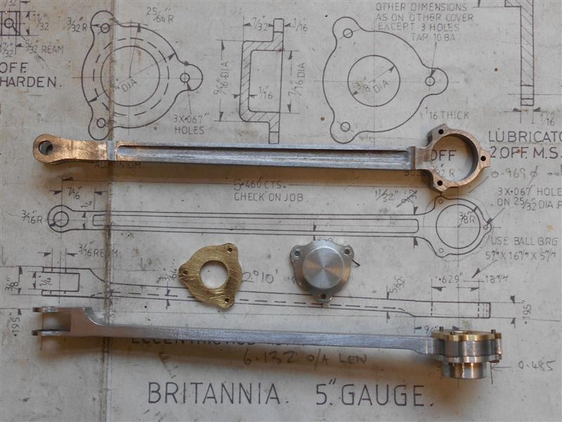
I've made the eccentric rods from some 1" x 1/2" black
bar but because of the offset some method had to be devised to get them
from the chosen material. Some quick maths indicated an angle of just over
two degrees so, after cleaning up the outside edges, the billet was loaded
to the vice resting on a two-degree angle block. The overall length was
then machined using a 12mm endmill and the top of the forked end milled
to clean up about 3/4" long. The quill DRO was set to zero and the other
end machined with the same tool for a length of about 1" and down to 0.375"
on the readout. I had previously obtained an accurate measurement for the
spacing of the bushes with a sliding gauge and the distance noted. |
 |
I drilled and bored the hole for the bearing first and
set this as the zero datum. The three bearing cover holes were drilled next
using the three-hole solution, and finally the hole in the fork end was
drilled and reamed 3/16" for the pivot pin at the recorded position. While
the milling vice was still on the table, the fork slot was cut with a 1/8"
slitting saw. . |
 |
 |
The billet was then turned over with the bearing end rested
on a 3/8" thick spacer and an anti-vibration wedge placed in the fork. The
two ends were then milled down to finished thickness. Most of the rest of
the surplus material was removed using carbide tooling before moving on
to the final shaping operations using fixtures to hold the work. |
 |
 |
I made a mandrel to fit the bearing bore on the lathe
and then transferred it to the rotary table on the mill. The three 10BA
holes were put in and the work bolted onto it to allow maching of the exterior
form of the bearing housing. This was done freehand with a 1/4" dia slot
drill, getting the diameter around the bosses first and the thinned sections
after. I re-used a general-purpose fixture for the final operations, using
a spacer to fit between the forks for the first end and a spacer under the
workpiece at the bearing end. By adjusting the position of the fixture I
was able to mill the sides of the rod to produce the taper required. The
rest of the shaping and fluting was done in similar fashion to the radius
rods. |
 |
| 12. Eccentric Rod Bearing Covers |
|
 |
The eccentric bearing has a back plate and front cover,
required because this is the only part of the motion that constantly rotates
a full circle whereas all the other parts are reciprocating. I made the
front "top hat" from some 1" dia aluminium alloy, facing and turning the
outside forms, then parting off at finished length. The parts were then
loaded to the chuck on the mill table and the centre removed with a succession
of slot drills. The 10BA clearance holes were also drilled at the 0, 120
and 240 degree positions. Finally, the fixture that I used to mill the shape
on the ends of the eccentric rods was reloaded to the chuck and the caps
bolted on. A 1/4" dia end mill was used to remove the material to create
the inner form, rotating the table from 60 degrees to plus and minus 33
degrees, similarly at 120 and 240. |
 |
 |
The back plates were made from 16swg brass offcuts, a
3/8" diameter hole drilled and reamed in each one. These were than loaded
to a mandrel in the lathe and turned to 0.970" dia, the outer size over
the bosses. The complete assembly was taken to the mill and loaded into
the chuck with the rotary table set at 0 degrees. The three holes were then
drilled at 1.4mm - 10BA core size - and the inner form milled as before,
although I found that I needed to plunge-cut to remove most of the material,
finishing by rotating the table. To finish, the components were bolted together
and the outside form of the bosses made using sanding drums in the Dremell |
 |
| 13. Cylinder Release Valves |
|
|
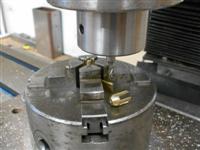 |
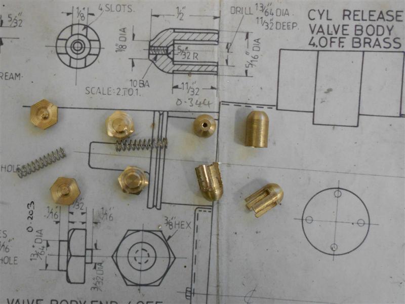
The bases of the dummy cylinder release valves were made
in a single operation from 3/8" hex brass bar, turning the large diameter
first, adding the chamfer and then forming the 3/32" dia locating spigot
with the parting tool. The parting tool was then moved along a further 1/16"
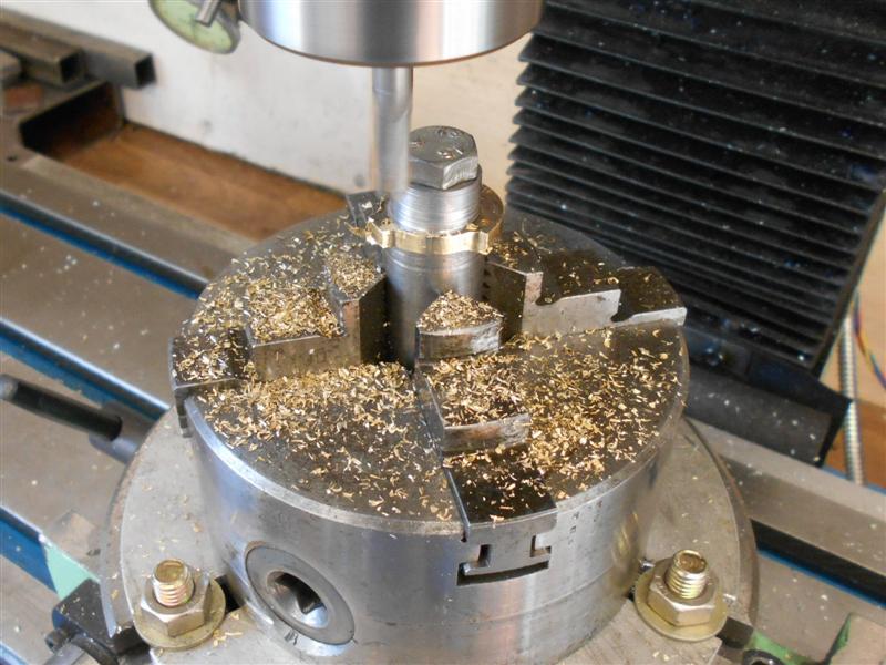
and the component parted off. I made the body from 5/16" diameter brass
bar as a bullet shape only, leaving the drilling for later. Moving to the
mill, I set up the self-centering 4-jaw chuck on the table and set the exact
centre on the DRO. The bodies were then inserted nose down and the 13/64"
diameter hole drilled to depth. Because I have changed the design slightly,
I also drilled a 1.8mm hole through instead of the 1.4mm for 10BA. |
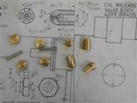 |
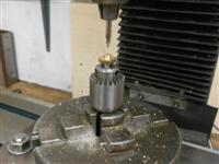 |
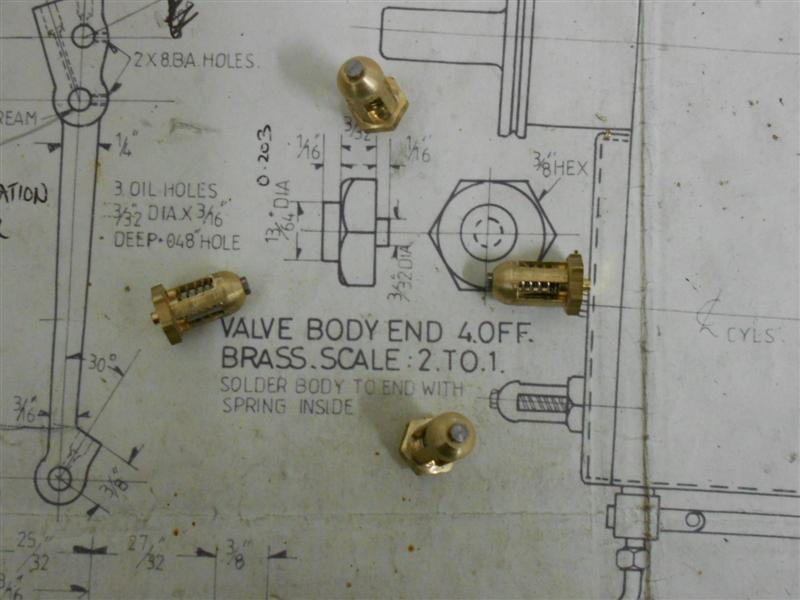
The next operation was to form the four slots and this
was done with a 1/8" diameter endmill, passing back and forth on the respective
centre-lines. This shows the reason for the choice of the 4-jaw chuck. A
small drill chuck was then set in the 4-jaw and the bases drilled 1.4mm,
holding on the 3/32" spigot. The 4-jaw chuck jaws wouldn't close down far
enough to hold the parts. They were then tapped 10 BA freehand using my
small tapping fixture. A pair of pen springs were cut in half and the three
components brought together with a 10 BA bolt through the centre. These
will be soldered to the cylinder front and rear covers once they have been
made. |
 |
| 14. Next item... |
|
|
| |
|
|