| Pump & Pipework |
| |
1. Main Pump Body |
|
 |
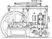
The pump body below the platform looks an
interesting part to build, comprising three sections joined by angled pipework.
The intake is to the side of the structure and the outlet is to the front. |
 |
The main body has a bulbous section which would be a doddle
to make on a CNC lathe but, in the old days (when I was a lad), before ball-turners
and copy-turning were common aids, a form tool would have been made to plunge-cut
the shape. So I made this first. Starting with a section of ground flat
stock (O1 oil-hardening tool steel), I first squared off the front with
the plate set at about 5° in the milling vice. The drawing shows the bulb
to have a diameter of 32mm so the boring head was pre-set to that size. |
 |
 |
The stem is shown as 20mm diameter either side so a dozen
plunge cuts at half-a-mil DOC were taken to leave the finished form. The
tool was then trimmed down to a usable size and hardened by heating to cherry-red
and plunging into cold water. A light touch on the side of a fine grinding
wheel to top-dress the tool and it's ready to cut. I don't bother tempering
tools when they are for cutting brass - personal choice that some will disagree
with, I'm sure. |
 |
| First op was to face and rough turn the o/d
to 34mm, leaving 6mm thickness up the flange end. Then it was reversed in
the chuck, faced to length and the flange and locating spigot finish-turned.
The bore was also drilled and reamed 10mm diameter. Over on the mill, the
six mounting holes were drilled 3.3mm diameter and the four gland cap holes
drilled and tapped M3. |
 |
 |
Then it was back to the lathe and the workpiece mounted
on a 10mm diameter mandrel. The first job was to turn the lower section
to 20mm diameter for about 8mm length. A radius tool was used to machine
the rear section to the same diameter and finish the flange to 4mm thickness. |
 |
 |
The form tool was set up and the bulbous section of the
pump body formed. Part-way through, I had to centre-drill the mandrel and
provide centre support, and the plunge cut had to be rocked gently side-to-side
to get a nice cut but, other than that, it all went suprisingly well. And
to finish this section of the pump, the body was returned to the mill and
the flats for the pipe-mounting positions milled to size. The cross-hole
was also drilled at this time. Using pins in the drilled holes made it easy
to get the two flats square to each other. |
 |
| |
2. Pump Valves |
|
 |
The pump assembly is shown as a fully-soldered affair
but I have chosen to solder each of the valves separately and bolt them
to the pump body. There is too great a risk of passageways becoming blocked
with stray solder and no means of cleaning them out. The outlet valve was
made from a block of bronze but only because I didn't have a suitable chuck
of brass. After machining the outside dimensions to size, the various holes
were drilled, tapped or reamed as appropriate. Rather than make a fixture
for the rotary table, I decided to use a radius cutter to machine the rounded
ends. This is just a cheap router bit but perfectly OK for machining brass. |
 |
 |
Since I was already making various M12 x 1 fittings, I
also made a mandrel and screwed the valve to it. The extended valve section
was then turned to the 18mm diameter specified. The inlet valve is a simple
cylinder and I didn't bother taking any pictures of that. The two angled
pipes were made next, starting with a pair of flanges turned from brass
bar and parted off 4mm long. These were held in a small chuck, using soft
jaws, which was then gripped in a tilt-and-turn vice. Alignment of each
part was by eye alone. |
 |
 |
A 12mm hole was cut in each, staring with a 4mm slot drill
and working up in 2mm increments. The two parts are at different angles
so each was completed separately. With the vice level, the fixing holes
were drilled 2mm diameter to accomodate 10BA screws (because I have loads
of them!) Two pieces of 1/2" brass bar were skimmed to 12mm diameter and
cut off overlong to allow for soldering and final shaping of the ends. A
solder ring was rested over the short protrusion and heat applied only to
the other side of the flange. |
 |
 |
The two sections were then held in the vice and the backs
skimmed to just clean the back faces. Packing was used to lift the sections
to avoid the ring of solder on the other side, and a stub of 5mm material
placed in the hole to prevent crushing of the pipe. After silver-soldering,
the brass is soft as putty. I felt the best way to shape the ends was to
bolt them to the pump body and use the boring head to form the ends. And
the best way to mount the pump body was to bolt it to the underside of the
cylinder mounting frame. Here's how the setup looked |
 |
 |
This is another picture of how the pump gets assembled
and better shows the difference in the two angled pipes. I still need to
make the inlet connection for the bottom it's valve. Because I have already
soldered the flange to the pipe, I need to be careful not to disturb this
joint whilst making the connection to the valve body. I'm using two clamps
here for a dual purpose, to hold the pipe in place and to act as a heat
sink to keep that end as cool as possible. A solder ring sits astride the
pipe and heating was done from the underside only. It took a little longer
than expected but, the moment the solder melted, I removed the heat and
let conduction finish the job. |
 |
 |
Same rules applied for the other valve, soldering the
pipe to the valve first, cleaning up in the pickle, then soldering the inlet
port afterwards. Again, careful application of heat to get it just hot enough
to melt the new solder without melting the ealier joints. Afterwards, each
pipe was drilled through into the body. The next picture shows my modification
to the pump body. Because of the angle of the pipe, I had to go for three
fixing screws whereas the shallower angle of the outlet valve on the right
allowed me to use four screws. I also cut a recess for an "O" ring rather
than use a gasket. It also shows that the solder joints have come out quite
successfully. |
 |
 |
So this is the full collection of parts for the main assembly
and, this time, the components are in the correct orientation. The pressure
bottle and assocciated parts are made but attach afterward through the platform.
I will use silicon nitride balls to seal the valves but they haven't arrived
yet.This is a picture of the fully-assembled pump mechanism, temporarily
attached to the cylinder mounting frame. |
 |
| |
3. Pressure Bottle |
|
| I've made the pressure bottle as a dummy to
make the machining easier. The fluted body has been made from a piece of
aluminium tube a little bigger than required. The flutes were cut with a
6mm round-nosed slot drill using a rotary table to index round 15d each
time. I made the first pass at 0.5mm, then went round again at 1.0mm depth. |
 |
 |
The top and bottom sections were made from brass bar and
I made a simple form tool from gauge plate to cut the radius. This was heated
to cherry red than dunked in cold water to harden. I don't bother to anneal
these tools but they can be a bit brittle so need care in handling. The
top is tapped M6 and a piece of stainless steel M6 studding screwed in tight.
The bottom is made in similar fashion but with a 6mm diameter hole through
and the leg section turned separately, tapped M6 and added after. The flange
was drilled 3mm diameter and the assembly bolted to the pump outlet. |
 |
| |
4. Next Item |
|
 |
Under Construction |
|